The design is very simple, simplest then the previous signal generator version. This new contains simple CMOS oscillator. The design is small, simple, and the output signal is perfect. The duty-cycle is always 50%, the amplitude of square signal is 5...15V if required. The frequency setting is very easy, on 10 MHz the square signal is really nice.

The red is the square output of CMOS circuit, the green is the triangle signal.

The triangle and the square signal is much better compared to the analog oscillator circuit.

This is the schematic, the difference between R1 and R2 is 10x, the capacitor can be very small value, the frequency is very stable.
Unfortunately, the upper ideal stage will be wrong if I continues the design with comparator circuit on the simulation. (See the schematic, I did not continued the triangle output to the comparator input). If the triangle signal after CMOS (or TTL) circuit wired to the comparator, the signal will be non-usable:

The square signal stay good, but the triangle signal going wrong on the simulation.

The usefulness triangle signal.

I did nothing else, I just continued the signal with comparator.
The upper problem can be solved with a small modification, see the images and the power source of the comparator on the schematic:


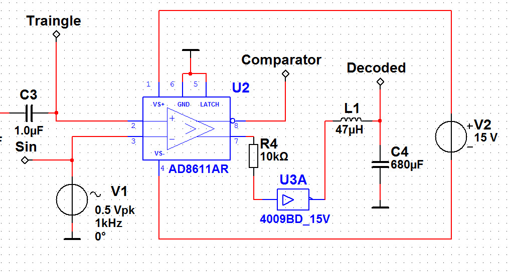
On the circuit, I using independent DC power source for comparator chip only. After I getting back the nice signals, but with this design the comparator doesn't made PWM signal from sources. If I used common ground, the comparator started to work, but the triangle (and the PWM) signal is going wrong again:

Transient analysis result when the CMOS oscillator and the comparator have common ground:


At this moment I don't know how to solve the problem on the simulator. I wonder, (and not sure) about the result of real circuit. The simulation is usefulness, but the oscillator design is better and simpler before using comparator. So at this moment, the analog oscillator design is much better than this new one.


 Posts
Posts


