The design is very simple, simplest then the previous signal generator version. This new contains simple CMOS oscillator. The design is small, simple, and the output signal is perfect. The duty-cycle is always 50%, the amplitude of square signal is 5...15V if required. The frequency setting is very easy, on 10 MHz the square signal is really nice.
Tuesday, August 28, 2012
PWM amplifier 1 - The PWM modulator design III.
The design is very simple, simplest then the previous signal generator version. This new contains simple CMOS oscillator. The design is small, simple, and the output signal is perfect. The duty-cycle is always 50%, the amplitude of square signal is 5...15V if required. The frequency setting is very easy, on 10 MHz the square signal is really nice.
PWM amplifier 1 - The PWM modulator design II.

Friday, August 17, 2012
PWM amplifier 1 - The PWM modulator design I.
But I have TAS5261 chips, without analog input. For this design required TAS55xx PWM modulators and analog/digital converters. These chips recommended for home DVD players, the power supply is 3.3 volts only. I don't think that this solution is ideal for instrument amplification.
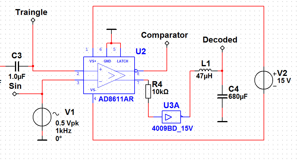
In this post, I writing about the method and simulation of analog PWM modulator.
First I need a triangle function generator. I found too much... The clock of PWM input TAS chip is 192-384 kHz, what is understandable if digital chips placed before chip. For this frequency, not too easy to find triangle signal generator with very good output.
Can be found one-chip function generators. One of them is LM566 (with this chip I found a schematic) not available here and now, or we can use XR2206 or ICL8038 chips. These chips are very simple solutions for triangle output, maybe I will try some of them. The maximum frequency on the datasheet is 0.5MHz, typical is 1MHz, but the 8038 have 300kHz maximum. I have no experiences with these function generator chips, so I don't know about the output quality. This is the reason, why I seek discreet analog function generator for triangle output. The another reason, is, function generator chips are not available on Multisim.
The first tryouts I have no success:
I have good result on 300kHz:
Monday, February 20, 2012
4 input headphone amplifier with TPA6120 chip
The schematic:

The device contains 4 audio inputs with volume adjustment. The input connector must be soldered to the bottom of PCB (blue) and the volume must be potentiometers soldered to the top (yellow) of PCB. The input and line output connectors can be 6.3mm jack OR stereo RCA connector. The headphone output can be 6.3mm jack only. The PCB contains header for 4 power filter circuits (whats are optional if not required) for 4 dual operational amplifiers. The operational amplifier chips are compatible with TL072 for cheapest solution, NE5532 for better quality, and with LT1124 for the best quality. These chips used for the input mixer, for unbalanced/balanced converters, and for the line output amplifiers.
The PCB design:

See also:
- More unbalanced to balanced converters
- Simulation of unbalanced-balanced converter
- 2 input headphone amplifier
- Headphone amplifier with TPA6120
| ||||||||||||||||||||||||||||||||||||||||||||||||||||||
Tuesday, January 24, 2012
Updates of PDF manuals
- TDA7293 modular project: modified the wrong parallel schematic and PCB module, and inserted offer to make amplifier up to 800W with more than one parallel modules. Two new PWM fan controller and speaker protection design included.
- Headphone amplifier with TPA6120: Two schematic for the simplest and full featured solutions, but four PCB designs available.
My next "project" is to finish PDF manual for my parametric EQ.
Download manuals from the right side.
Tuesday, December 13, 2011
Modular TDA7293 bridge/parallel amplifier
- Single amplifier with only one module with 1 TDA7293 or TDA7294 / channel
- Bridged amplifier with 2 modules / channel
- Paralleled amplifier with 2 modules / channel
- Combined bridged and paralleled with 4 modules / channel
- Paralleled simple or bridged amplifier, but with 2 paralleled module
The official datasheet contains all modes of TDA729x circuits. The TDA7294 is very cheap, but cannot use for paralleled mode, and no clipping led output. The recommended max. power supply voltage is +-40V. The TDA7293 have paralleled mode (where only the power stage works, the preamp stages off), the max. power supply voltage is +-47V, and clipping led output available. The maximum output power of one circuit is 70-75W of TDA7294, and about 80-100W of TDA7293.
The possible output powers of bridged application:

The V column is the power supply voltage, 1 means: 1 IC paralleled, 2 means: 2 IC paralleled with all others. Without superscripted number have no parallel connections, this is only bridged.
The possible output power with single (non bridged) application:

The V is the power supply voltage, 1 means: 1 IC paralleled, 2 means: 2 IC paralleled. Without superscripted number have no parallel connections.
The bridged or single version is very popular on "official" instrument amplifiers. Carlsbro GLX100, Marshall MG, and Marshall Mode Four contains TDA7293/7294 circuits. I using bridged application long time ago for stereo guitar amplifications and for microphones. This is more than enough for small rooms or rock clubs for live sessions with very good (for example Eminence) speakers.
The four modules (including speaker protection) can be connected by the 15 pin connectors soldered to the edge of the PCB. This is the method to build single, bridged, paralelled, bridged+paralleled, bridged+duble-paralleled, mono or stereo applications with very simple easy to build PCBs.
The first and the most important circuit is complete 70-75W amplifier:

This circuit always be the first of the complete amplifier configuration, which can be continued with parallel, bridge, or speaker protection module.
The PCB of main TDA module:

To the Conn2 on right edge can be connected another module for bridged or parallel application. It this one main module required (for 75W output power) then Conn2 can be used for speaker protection, but this is not required. The nother side have Conn4 connector for the second (right) channel is the setup is stereo. This Conn4 connector can be connected the speaker protection only. For example the simplest stereo setup is: 1 main module for left channel, 1 speaker protection, 1 main module for the right channel. Examples are on the PDF manual. The speaker protection will be protected bot left and right channels.
On this first PCB the Conn5 connector is the stereo audio level inputs, the right channel wired to the input of another main module on the right side of speaker protection. The output connector Conn6 is not stereo. This connector can be user for one channel only (the another output is on the second main module). The single setup uses Out+ and GND, the bridged setup uses Out+ and Out- for speaker connection.
The second circuit for bridge configuration:

And the bridge PCB:

The Conn4 connector of this bridge PCB can be used for the connection of first main circuit. This module can be continued by Conn5 connector with speaker protection (if the channel finalized) or with parallel module if more output current needed.
If the setup must be continued with parallel mode, here is the schematic:

PCB for parallel mode:

This is the simplest module, because the premaplifiers are off within the circuit, only the power FETs working. This mode controlled by Buffer Driver and Slave mode pins of TDA circuit. This module can be connected to the right side of main module, bridge module, or if required can be connected to the parallel module to duplicate the paralleled circuits within the application. The second parallel modules can be continued with speaker protection or with nothing only. The another edge of the speaker protection (if used) can be restart the full setup with main module for right channel.
The speaker protection:

And the PCB:

Here are the examples how to build complete amplifiers with several output powers with these four modules. The "Module 1" is always the first and always required main module, the "Module 2" is the optional bridge module, "Module 3" is the optional parallel module can be duplicated within the setup, and the 4th is the speaker protection.
The simplest mono setup (75W on 4 Ohm, with 8 Ohm about half):
- Module 1
- Speaker protection (optional)
Simple stereo setup (2x 75W on 4 Ohm, with 8 Ohm about half):
- Module 1
- Speaker protection (required)
- Module 1
Mono bridged application (8 Ohm only, about 150W):
- Module 1
- Module 2
- Speaker protection (optional)
Bridged stereo setup (8 Ohm only 2x150W)
- Module 1
- Module 2
- Speaker protection
- Module 1
- Module 2
Mono paralleled setup (4 Ohm about 100W):
- Module 1
- Module 3
- Speaker protection (optional)
Stereo paralleled setup (2 x 100W on 4 Ohm):
- Module 1
- Module 3
- Speaker protection (required)
- Module 1
- Module 3
Mono bridged and paralleled (4 Ohm - 300W, 8 Ohm 200W):
- Module 1
- Module 3
- Module 2
- Module 3
- Speaker protection (optional)
Stereo bridged + paralleled setup (About 2 x 300W on 4 Ohm):
- Module 1
- Module 3
- Module 2
- Module 3
- Speaker protection
- Module 1
- Module 3
- Module 2
- Module 3
The parallel module can be connected to the first parallel module for duplication. This increases the maximum current, maybe smaller output impedance possible.
Doubled parallel bridge setup:
- Module 1
- Module 3
- Module 3
- Module 2
- Module 3
- Module 3
and the upper setup can be continued with speaker protection and the another edge of speaker protection can be repeated the same setup for right channel is stereo application required.
See also:
- Failure in the official datasheet of TDA7293
- TDA7293 for more than 300W
- New PWM Fan controller with speaker protection
- PDF manual for TDA7293 amplifiers
| ||||||||||||||||||||||||||||||||||||||||||||||||||||||||||||||||||||||||||||||||||||||||||||||||||||||||||||||||||||||||||||||||||||||||||||||||||||||
Friday, November 18, 2011
2 input headphone amplifier with TPA6120
Because I would like to use all possible features with all-in-one PCB:
- Small transformer placed to the PCB, with 2 independent symmetrical +/-15V outputs. This is because separated power possible for left and right channels.
- 2 inputs on the PCB with volume control and jack or RCA inputs.
- Master volume and output jack.
- Mini audio mixer after inputs.
- After the mixer, unbalanced/balanced converter.
The new schematic:

The transformer and the voltage regulators placed to the PCB, with two independent outputs with 4 regulator devices. With inputs, you can choose what you like, 2 pcs 6 .3mm jack, or stereo RCA. Maybe 1 jack and 1 RCA. The balanced converter make better quality and more volume.
This is the PCB:

The longer side of PCB is about 15cm. Around the inputs have something "chaos". You can choose between RCA and Jack inputs this is the reason why 2 footprints on one place, but the inputs have to be placed to the bottom side (must be soldered on the top) and the volume potentiometers placed to the top layer (must be soldered on the bottom). But I think this is no problem on assembly. Because the transformer is on the board, 230V must be connected to the header called "Conn2". The regulators on the edge of the board can be screw to the wall of case or to heatsink. 3 "power filter" circuits required as module for this board, one for mixer, 1-1 for left/right unbalanced/balanced converter.
See also:
- 4 input headphone amplifier with line output
- More unbalanced to balanced converters
- Simulation of unbalanced-balanced converter
- Headphone amplifier with TPA6120
| ||||||||||||||||||||||||||||||||||||||||||||||||||||||
Wednesday, November 9, 2011
Headphone amplifier with TPA6120

The headphone circuit is very simple. With unbalanced balanced converter is much better, but in this first version this feature is missing from these PCB-s. I have design with unbalanced/balanced converter, but for modular mixer only. Now I posting about "independent" headphone amplifiers. Fortunately, this circuit is not the smallest SMD footprint. The distance between foots is 50 mill, the foot width is 20 mill. This size is no problem for homemade prototype.
The main IC is:
This chip have 20 "foots", but the half of these pins are not internally connected. On the bottom, small heatsink available, but this is not only heatsink, this is the GND as 21st pin. Footprint not available, have to be draw on the CAD software. The full circuit without dual power supply, and unbalanced/balanced converter is very simple:

These modifications possible:
- For both channels (left and right) have + and - inputs for balanced sources. This is optional,
but maybe the result is better. On this schematic has no input for balanced sources. - Separated dual power supplies possible for this one circuit. this is reduces the crosstalk between left and right channel. The dynamics of this circuit on the official datasheet is 120 dB, what is very good if true. Class D amplifier. I have "power filter" circuit to separate power sources of left and right channels, but I don`t want to use this for headphone amplifier because maybe the current source is not enough.
Therefore I have 3 versions of PCBs:
The first is the biggest one, to screw with another preamplifier circuits. The position of rear hole is the reason why this PCB so large:

If the same hole positions are not important between preamplifiers and the headphone amp, then here is the smaller PCB:

Finlay I have smaller. This PCB have separated inputs for balanced inputs of left and right channels, and inputs for left and right powers. this is the reason why volume potentiometer missing, and the power filter capacitors are too:

This is the smallest PCB, but possible to use after unbalanced/balanced converter and with separated dual power supply. But these solutions are required with another circuits.
6.3mm jack input soldered to all of these boards, the 1st and 2nd version of PCB have volume potentiometers too. This volume pot missing from the 3rd version, because the pot must be soldered before unbalanced/balanced converter. The TPA6120 circuit fitted to the bottom layer of all PCBs (this is the reason why this part mirrored), all another placed to to top.
See also:
- More unbalanced to balanced converters
- Simulation of unbalanced-balanced converter
- 2 input headphone amplifier
- 4 input headphone amplifier
| ||||||||||||||||||||||||||||||||||||||||||||||||||||||||||||||||||||||||||||||||||||||||||