Showing posts with label Modular. Show all posts

Tuesday, January 17, 2012

Modular, expandable parametric equalizer based on UREI546

I posted about the equalizer called UREI545 and UREI546. This is the one of my favorite project. These devices are not same, but very similar. The differences between 545 and 546, the LP/HP filter on the input, and the number of bands. On the original UREI545 have 3 parametric EQ filters, and one switchable filter with 3 different middle frequencies. The UREI546 have 4 bands without switchable frequencies, but this is dual device. Can be used as mono 8 band parametric EQ, or as 4 band stereo parametric EQ. These devices used by musicians for guitar and vocal equalization.

The current project based on the UREI546, but modified. The new design is an expandable parametric equalizer with modular system for smaller PCBs with no limitations. The maximum number of bands are not limited, but the current project made for 4 to 8 band equalizer, with optional input and output gain modules, optional HP/LP filter module, and optional clipping LED module. The design is similar as my previous modular expandable audio mixer or modular amplifier. The current project started with software simulation of filter circuit, and continued to get capacitor values for 8 band EQ by simulation. This is the post where I publish the schematic and PCB design of expandable modular parametric equalizer.

For the expandable feature, 2 mainboards required for this project. The first is for 4 modules, contains connectors for inputs (Conn2), outputs (Conn3), and +/-15V power supply (Conn1). This mainboard designed for 4 band EQ only, without additional modules:

Because between EQ modules and other modules requires serial connection, (not parallel like in the modular audio mixer), the last module on the whole system must be connected to the output bus. This is the reason why W1 and W2 jumpers are required. With these jumpers, the last module must be wired to the system output, without jumpers, the output of module connecting to the input of next module. The jumper must be used only on the last EQ or Output Gain module of the whole system. The connector P2 is 10 pin female connector, the next mainboard must be connected here if required. Conn4....Conn7 is 2x6 L headers for the EQ or Gain modules.

The PCB of first mainboard:


The second mainboard is more simple, contains only one 2x6 L header for one module, on the left one 10 pin male connector, on the right one 10 pin female connector:

W1 and W2 jumpers must used if the connected module is the last on the whole system. If last, the current module output connected to the system output bus by W1 and W2. The one and only exception, if the last module is the clipping detector. If more modules required, this mainboard must be connected to the previous one.

The PCB design:


The modules can be soldered to these two mainboards with 2x6 pins L header. The most important module is the parametric filter:

This filter based on UREI546 with some modifications. The Conn2 must be connected to the mainboard, the Conn1 is the connector for "power filter" module for less noise. This is the reason why the filter capacitor missing from the OpAmp. The C3 is coupling capacitor, 10uF or 22uF is better than 100nF in the original design. No need to change on several EQ modules. For EQ bands with different middle frequency, only 2 pieces of Ca capacitors must be changed. This is the reason, why the footprint accept 200 and 300 mil pins. Sw1 is the bypass switch, D2 diode is connected for the clipping detector bus. P1 adjust Q, P2 adjust the middle frequency, P3 adjust cut/boost of the EQ module.

The PCB:

The module cutted on the bottom because this required for mechanical assembly. The bypass switch and the 3 required potentiometers are soldered to the PCB. D1 is the connector for LED displays the bypassed or connected status of the module. The both mainboards made for stereo circuits, but this module (and currently all others) is mono. The reason of this difference, that in the future I would like to design stereo filters for stereo EQ, but I would like to use these mainboards. The lion in the way, that 4 potentiometers required to adjust the frequency if this EQ module going stereo.

The most important question about this module, the values of Ca (C1 and C2) capacitors. These values depend on the required middle frequency. I have no math expression, but I done software simulation for 8 bands with values.

  • Math expression required to get frequency values among the lowest and highest bands. This expression is used for Excel spreadsheet if the first and last frequency, and the number of other bands decided:
    =IF(C8<$D$5,$D$3*10^((LOG10($D$4)-LOG10($D$3))*(C8-1)/($D$5-1)), IF(C8=$D$5,$D$4,IF(C8>$D$5," ","?")))
  • The next is that we need the Ca capacitor value for the module frequency. This value is linear on the logarithmic scale with the frequency, but the best method is the software simulation. Here is an example for 8 band equalizer:

    The input of this spreadsheet is on the green fields on the top, contains the highest frequency of the first and last modules, and the number of all EQ modules. I always working with the highest frequency, the middle and the lowest value getting by the software simulation using modified standard capacitor values.
  • The real value of the module frequencies depend on the standard values of the capacitors. The best result is the software simulation again to getting the lowest and highest values of filters:
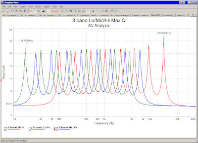
  • The number of possible requirements are very high. Not only the number of EQ bands, the lowest and highest frequency of the bands can be different. This is the reason, why I can publish and simulated 8 band EQ only. If you like another versions, for example less or more bands, or higher frequency of the lower band, software simulation required to get the capacitor values and the resistor values to setting Q.
The next module is a high pass/low pass filter circuit. I made little modifications compared to original one. About the LP/HP filter simulation see my next post. The current schematic with capacitor values:

With this design the bypass switch with LED, and the header for power filter are available too. The output connected to the clipping detector via D2, like all other filter modules. The C1 capacitor changed to 47pF to get better Q for higher frequency of LP filter. The potentiometers changed from 55kOhm to 22kOhm for smaller adjustment range. High adjustment range is not too important, because numerous adjustable filters can be connected after this module. The highest value of filter depend on C2 and C3 capacitor, what changed from 6.8nf to 4.7nF, but maybe 5.6 nF is the best because the new endpoint of frequency range is around 40kHz what is too much, but the original is around 15 kHz, what is low.

The capacitors of high pass filer is C4 and C5 changed to 470nF instead of the original 220nF to get lowest frequency. With this new value the filter starts from 15Hz, what is too low. Maybe 330nF would be the best, I will do simulation for several values soon.

The result of current AC analysis (470nF and 4.7nF):


The PCB of LP/HP filter module:


The next is a very simple and noiseless preamplifier module with jFET. I really like the sound of this circuit for guitar. This module can be used as first module (for input gain) and (or only) at the end of device as output gain:

This circuit can be bypassed by the switch, and can be ignored if not required.

The PCB:


The last module is the clipping detector what monitor all outputs of applied modules by the pin2 of 2x6 L header:


Clipping detector PCB:


The power filter, required for all modules for less noise except clipping detector:


I have 8 versions of power filter PCB where the difference is only the size of board. This is the version 6 with SMD resistors and transistors:


The required power supply and the PCB:


By these boards can be built like this (for example):

  • 4 bands mainboard, 4 pieces of EQ filters with the oroginal values of UREI546 can be the clone of original device but without preamplifier module, LP/HP filter, and clipping detector.
  • Start the whole device with 4 band mainboard, use the jFET gain module first, the second is the LP/HP filter module, and continue with 2 parametric EQ module. Connect mainboard 2 to mainboard 1, and use parametric EQ modules. When the maximum number of EQ modules connected, use one more jFET gain module for output gain (with W1 and W2 jumpers) and the last possible module is the clipping detector.

By software simulation the result of these circuits can be changed. The schematic samples on this post maybe set to wide values, but all modules adjustable, so I think this is not a big problem.

On the EQ modules and LP/HP filter modules maybe very important the logarithmic potentiometers. The resistor and capacitor values are linear, but with logarithmic scale of graph. On the simulation and on the schematic I used TL071...TL074, but for the best quality I offer using LT or NE series instead, what is much better for filter designs. For example for single OpAmp use LT1028/LT1128/LT1115, for quad or dual OpAmps can be changed to LT1124/LT1125.

See also:

PCB sales of this project
Module name Size
(mm)
Area
(cm2)
PDF SCH PCB image Tested Price (US$)
Des./3D Sim.1 Full2 Sim.1 Full2 Man3
4 band filter board V:1
88x55 48 - Yes Yes - - -
8
16 Ask
1 band filter board V:2 25x48
12 - Yes
Yes -
-
-
4 11 Ask
Parametric filter module
66x83 55
- Yes
Yes -
-
- 9 17 Ask
LP/HP filter module
66x63 42 - Yes
Yes
- -
- 7 15 Ask
I/O gain module
66x47 31 -
Yes
Yes -
- - 6 14 Ask
UREI clipping detector
22x34
7 - Yes
Yes
-
-
- 3 11 Ask
Power filter V:6 SMD
17x24
4 - Yes Yes - - -
3 11 Ask
Power supply
212x57 69 - Yes Yes
Yes - -
11 20 Ask
How to order? Please read the rules carefully!

Tuesday, December 13, 2011

Modular TDA7293 bridge/parallel amplifier

I finished the project of the most simplest and cheaper modular instrument amplifier. The final amplifier have output power between 70W and 300W for 4 and 8 ohm speakers. Three several modules required for this project if bridged and paralleled modes required. The 4th module is the speaker protection. The amplifier can be built as:
  • Single amplifier with only one module with 1 TDA7293 or TDA7294 / channel
  • Bridged amplifier with 2 modules / channel
  • Paralleled amplifier with 2 modules / channel
  • Combined bridged and paralleled with 4 modules / channel
  • Paralleled simple or bridged amplifier, but with 2 paralleled module
The modules can be connected with 15 pin connectors instead of wires. The single, bridged, and paralleled amplifier modules are not same, one for the first and the most important "main" module, one for bridge connection, and one for parallel connection what can be used for both main and bridged modules. The last 4th module is the speaker protection, must be placed to the middle of stereo configuration between left and right channels.

The official datasheet contains all modes of TDA729x circuits. The TDA7294 is very cheap, but cannot use for paralleled mode, and no clipping led output. The recommended max. power supply voltage is +-40V. The TDA7293 have paralleled mode (where only the power stage works, the preamp stages off), the max. power supply voltage is +-47V, and clipping led output available. The maximum output power of one circuit is 70-75W of TDA7294, and about 80-100W of TDA7293.

The possible output powers of bridged application:


The V column is the power supply voltage, 1 means: 1 IC paralleled, 2 means: 2 IC paralleled with all others. Without superscripted number have no parallel connections, this is only bridged.

The possible output power with single (non bridged) application:

The V is the power supply voltage, 1 means: 1 IC paralleled, 2 means: 2 IC paralleled. Without superscripted number have no parallel connections.

The bridged or single version is very popular on "official" instrument amplifiers. Carlsbro GLX100, Marshall MG, and Marshall Mode Four contains TDA7293/7294 circuits. I using bridged application long time ago for stereo guitar amplifications and for microphones. This is more than enough for small rooms or rock clubs for live sessions with very good (for example Eminence) speakers.

The four modules (including speaker protection) can be connected by the 15 pin connectors soldered to the edge of the PCB. This is the method to build single, bridged, paralelled, bridged+paralleled, bridged+duble-paralleled, mono or stereo applications with very simple easy to build PCBs.

The first and the most important circuit is complete 70-75W amplifier:

This circuit always be the first of the complete amplifier configuration, which can be continued with parallel, bridge, or speaker protection module.

The PCB of main TDA module:


To the Conn2 on right edge can be connected another module for bridged or parallel application. It this one main module required (for 75W output power) then Conn2 can be used for speaker protection, but this is not required. The nother side have Conn4 connector for the second (right) channel is the setup is stereo. This Conn4 connector can be connected the speaker protection only. For example the simplest stereo setup is: 1 main module for left channel, 1 speaker protection, 1 main module for the right channel. Examples are on the PDF manual. The speaker protection will be protected bot left and right channels.

On this first PCB the Conn5 connector is the stereo audio level inputs, the right channel wired to the input of another main module on the right side of speaker protection. The output connector Conn6 is not stereo. This connector can be user for one channel only (the another output is on the second main module). The single setup uses Out+ and GND, the bridged setup uses Out+ and Out- for speaker connection.

The second circuit for bridge configuration:


And the bridge PCB:


The Conn4 connector of this bridge PCB can be used for the connection of first main circuit. This module can be continued by Conn5 connector with speaker protection (if the channel finalized) or with parallel module if more output current needed.

If the setup must be continued with parallel mode, here is the schematic:


PCB for parallel mode:


This is the simplest module, because the premaplifiers are off within the circuit, only the power FETs working. This mode controlled by Buffer Driver and Slave mode pins of TDA circuit. This module can be connected to the right side of main module, bridge module, or if required can be connected to the parallel module to duplicate the paralleled circuits within the application. The second parallel modules can be continued with speaker protection or with nothing only. The another edge of the speaker protection (if used) can be restart the full setup with main module for right channel.

The speaker protection:


And the PCB:


Here are the examples how to build complete amplifiers with several output powers with these four modules. The "Module 1" is always the first and always required main module, the "Module 2" is the optional bridge module, "Module 3" is the optional parallel module can be duplicated within the setup, and the 4th is the speaker protection.

The simplest mono setup (75W on 4 Ohm, with 8 Ohm about half):
  1. Module 1
  2. Speaker protection (optional)

Simple stereo setup (2x 75W on 4 Ohm, with 8 Ohm about half):

  1. Module 1
  2. Speaker protection (required)
  3. Module 1

Mono bridged application (8 Ohm only, about 150W):

  1. Module 1
  2. Module 2
  3. Speaker protection (optional)

Bridged stereo setup (8 Ohm only 2x150W)

  1. Module 1
  2. Module 2
  3. Speaker protection
  4. Module 1
  5. Module 2

Mono paralleled setup (4 Ohm about 100W):

  1. Module 1
  2. Module 3
  3. Speaker protection (optional)

Stereo paralleled setup (2 x 100W on 4 Ohm):

  1. Module 1
  2. Module 3
  3. Speaker protection (required)
  4. Module 1
  5. Module 3

Mono bridged and paralleled (4 Ohm - 300W, 8 Ohm 200W):

  1. Module 1
  2. Module 3
  3. Module 2
  4. Module 3
  5. Speaker protection (optional)

Stereo bridged + paralleled setup (About 2 x 300W on 4 Ohm):

  1. Module 1
  2. Module 3
  3. Module 2
  4. Module 3
  5. Speaker protection
  6. Module 1
  7. Module 3
  8. Module 2
  9. Module 3

The parallel module can be connected to the first parallel module for duplication. This increases the maximum current, maybe smaller output impedance possible.

Doubled parallel bridge setup:

  1. Module 1
  2. Module 3
  3. Module 3
  4. Module 2
  5. Module 3
  6. Module 3

and the upper setup can be continued with speaker protection and the another edge of speaker protection can be repeated the same setup for right channel is stereo application required.

See also:

PCB sales of this project
Module name Size
(mm)
Area
(cm2)
PDF SCH PCB image Tested Price (US$)
Des. Sim.1 Full2 Sim.1 Full2 Man3
TDA 7293 main module 59x65 38 Yes Yes Yes - - No 7
15 Ask
TDA 7293 bridge module 44x50 22 Yes Yes Yes - - No 5 12 Ask
TDA 7293 parallel module 41x47 19 Yes Yes Yes - -
No 5 12 Ask
Dual speaker protection 51x42 21 Yes Yes Yes - -
No 5 12 Ask
PWM Fan controller V:1 70x57 40 Yes Yes Yes - -
No 7 15 Ask
PWM Fan controller V:2 56x57 32 Yes Yes Yes - -
No
6 14 Ask
Stereo bridged TDA7294 amp (2x200W + speaker protection)
77x184 142 Yes Yes Yes Yes -
Yes
21 - Ask
Power supply for poweramps
135x98 132 Yes Yes Yes Yes -
Yes
19 - Ask
Soft start for toroid transformers
67x67 45 Yes Yes Yes Yes -
Yes
8 - Ask
How to order? Please read the rules carefully!

Tuesday, November 15, 2011

Expandable, modular audio mixer for any number of channels

This is my second audio mixer project. The difference between current and previous design is, that this design can be expandable to any number of channels, the previous is made for 4 or 8 input channels only. At the end of the PDF manual of this project I inserted examples how to build audio mixer for any number of input and output channels.

I made paper models of my design to check how possible to build the complex device:


This gallery is funny, but very cheap to find mechanical problems before manufacturing the PCBs. With this test, I detected the problem, that the PCBs of "power filter" circuits are too big, have to be smaller than 25mm. This is the reason why I have 5 several power filter PCBs, and here is the smallest, with 22mm height, and 25mm width for the modular mixers:


The schematic of power filter module to decrease the preamplifier's noise and the crosstalk between left and right channels:


This PCB is very small, much harder to build....

The required preamplifiers for input channels are exactly same as than my simplest mixer project. The new on this design, that the small mainboards can be expanded with female/male connectors to build bigger than 8 channel audio mixer.

The first module of expandable mainboard:


...and the PCB for the first mainboard module:


This design is simple 4 channel audio mixer. Possible to finalize with 4 several preamplifiers. The blue potentiometers on the bottom of PCB is the L/R balance adjustment, but these parts are ignorable if not important. These potentiometers have blue color, because must be soldered to the bottom layer. There are mono, metal case parts. The first mainboard contains connectors for powers, phantom powers, line outputs, and balanced microphone input for all channels if mic preamp inserted. The main difference is the P1 female connector. This is the part where possible to connect another mixer mainboard to make more input or output channels. This first 4 channel module working without another connected boards, but on this one no connectors for outputs, only one stereo line output on the PCB via H5 connector.

For more inputs, here is the required module can be connected to the right edge of the first board to the connector P1:


and the really small PCB with P21 male connector:


This is an input channel for 2 arbitrary preamplifiers. Upper left is the male connector can be connected to the first, to the same, or to the output boards too. Here is the reason why expandable this device to any input or output channels.

If output channels required, here is the new schematic:


And I have 2 PCB design for upper schematic:


The difference between two PCBs is the L/R balance potentiometer only. This mainboard-module made for output circuits. The board can be connected to anywhere and anytime within the whole system. I offer several output modules:

The line outputs with master volume adjustment:


...and the PCB:


The difference between this, and the previous version of line output board, that this board contains line driver circuits, not the mixer's mainboard. This board contains adjustable master output of mixer with volume potentiometer with following variations:
  • 2 6.3mm jack
  • 1 6.3mm and 1 3.2mm jack
  • 1 6.3mm jack and 1 stereo RCA
  • 1 3.2mm jack and 1 stereo RCA
This board contains only one stereo volume adjustment, but possible to soldering to the board with L/R balance potentiometer if this feature required.

Another output circuit:

This is headphone amplifier with TPA6120. I modified my previous design of this module.

The PCB:

This is the simplest application of this really good IC with 6.3mm jack output and volume adjustment feature.

I made another version of this output for my audio mixer. The difference, here is an unbalanced/balanced converter for less noise, higher dynamics, higher possible volume. The official 120dB dynamics range is really high quality.


The required PCB is bigger, with two power filter module on P3 and P4 connectors:


PCB sales of this project
Module name Size
(mm)
Area
(cm2)
PDF SCH PCB image Tested Price (US$)
Des. Sim.1 Full2 Sim.1 Full2 Man3
Power filter module
17x25 4 Yes Yes Yes - - No 3
11 Ask
1st mixer module
103x95 98 Yes Yes Yes - - No 15 24 Ask
2nd mixer module
51x93 47 Yes Yes
Yes - - No 8 16 Ask
3rd mixer module
26x93 24 Yes Yes
Yes
- -
No 5 13 Ask
Line outout board
65x76 49 Yes Yes Yes - -
No 9 16 Ask
Headphone output board
56x71 40 Yes Yes
Yes
-
- No
7 15 Ask
Balanced headphone output board
58x105
61 Yes Yes
Yes -
-
No 10 18 Ask
Microphone preamp module V2
67x103
69 Yes Yes
Yes
Yes
-
No 11 19 Ask
Microphone preamp module V3
67x103
69 Yes Yes
Yes -
-
No
11 19 Ask
1 dual opamp preamp module
61x103
63 Yes
Yes Yes
-
-
No 10 18 Ask
2 single opamp preamp module
64x103 66 Yes
Yes
Yes
Yes
-
No 11 19 Ask
HQ 2 single opamp module
67x103
69 Yes
Yes Yes
-
-
No
11 19 Ask
jFET guitar preamp module 65x102 66 Yes Yes
Yes -
-
No 11 19 Ask
Switch module
18x34 6 Yes Yes
Yes Yes
-
No 3 11 Ask
Simple Power supply
121x57
69
Yes
Yes
Yes Yes
-
No 11 20 Ask
Power supply with 48V phantom
168x89 150 Yes Yes
Yes -
-
No 22 32 Ask
How to order? Please read the rules carefully!

Modular audio mixer for 8 and 4 input channels

I uploaded two new PDF documents about my audio mixer projects (1 - 2). The circuit called "audio mixer" is really simple, the required preamplifiers are little harder, if you need poweramp and EQ the device will more harder. But already I have tested and passed preamplifier project with headphone amplifier. And I have two modular equalizers ready to build. So I need audio mixer to collect these circuits to the simplest solution.

As I wrote already I have two of audio mixer project, because first time I designed very simple, with 4 or 8 input channels only, with master volume and line two outputs only. This project contains 2 very simple mainboards for 4 and 8 channel inputs, two output panels, and preamplifiers as module. The preamplifiers for mixer is same as my first designs, but can be connected with 12 pin male connectors to selected mixer mainboard.

For example, here is the microphone preamplifier with INA217:


The "original" PCB for this device is here:


But for modular mixer I have to modify the board design, the input and power connectors are removed, and changed to P4 connector on the bottom of board:


These preamplifier modules are smaller than the original versions, and contains "power filter" circuits as module (P5 and P6 connector at upper board). The preamplifier modules can be connected to the mixer mainboards, any preamplifier can be connected to the any connector of the mixer. The distance between preamplifiers is 25mm. This is the reason, why I have to design new versions of PCB for circuit called "power filter". This module must be smaller than 25mm. I have 5 versions of this module, with several sizes. All my preamplifiers (mic preamp with INA217, stereo dual jFET preamp, Dual OpAmp, 2 versions of single OpAmp) re-designed for modular mixer system.

The picasa gallery:


For the simplest version of my mixer project I have two mainboards with connectors for preamps, outputs, power supply, and balanced inputs for microphones:


4 channel mainboard for 4 inputs and 2 outputs:

For this board required 2 "power filter" modules, 4 preamplifiers, 1 volume board, and 1 line output board.

For the board can be connected two output PCBs. The one is for the master volume:

This PCB must be soldered after the 4th preamplifier via P5 male connector. This board working as 2 separated volume potentiometer for left and right channel, and possible to use only one stereo potentiometer for both channels on the pins of P1.

The another output module made for 2 line level outputs:

This board must be soldered to the last connector of mixer board via P1 header. The line level circuit designed to the mainboard, so this PCB contains the connectors only. The board useful for:
  • 2 6.3mm jack
  • 1 6.3mm jack and 1 stereo RCA
  • 1 6.3mm jack and 1 3.2mm jack
  • 1 3.2mm jack and 1 stereo RCA
The main output of full mixer is connected to the mainboard. This is the output for equalizers, poweramps, headphone amps, etc....

I designed 8 channel mainboard:


This circuit is same as than the upper 4 channel design. But here is 8 connectors for input channels can be connected to preamplifiers. The two of output boards is same too. This board width is 25cm, I think this is something big, very hard to manufacture, this is the reason why i designed "expandable" version of my audio mixer with connectable small mainboards for more than 8 channel inputs.

PDF manuals for audio mixers:
PCB sales of this project
Module name Size
(mm)
Area
(cm2)
PDF SCH PCB image Tested Price (US$)
Des. Sim.1 Full2 Sim.1 Full2 Man3
Power filter module
17x25 4 Yes Yes Yes - - No 3
11 Ask
4 channel mixer mainboard
149x84 125 Yes Yes Yes - - No 19 28 Ask
8 channel mixer mainboard
240x80 192 Yes Yes
Yes - - No 27 36 Ask
I/O board
37x60 22 Yes Yes
Yes
- -
No 5 12 Ask
2 Potmeter board
31x62 19 Yes Yes
Yes
-
- No
5 12 Ask
Microphone preamp module V2
67x103
69 Yes Yes
Yes
Yes
-
No 11 19 Ask
Microphone preamp module V3
67x103
69 Yes Yes
Yes -
-
No
11 19 Ask
1 dual opamp preamp module
61x103
63 Yes
Yes Yes
-
-
No 10 18 Ask
2 single opamp preamp module
64x103 66 Yes
Yes
Yes
Yes
-
No 11 19 Ask
HQ 2 single opamp module
67x103
69 Yes
Yes Yes
-
-
No
11 19 Ask
jFET guitar preamp module 65x102 66 Yes Yes
Yes -
-
No 11 19 Ask
Switch module
18x34 6 Yes Yes
Yes Yes
-
No 3 11 Ask
Simple Power supply
121x57
69
Yes
Yes
Yes Yes
-
No 11 20 Ask
Power supply with 48V phantom
168x89 150 Yes Yes
Yes -
-
No 22 32 Ask
How to order? Please read the rules carefully!