I made this movie how I made very good quality prototype PCB with soldering mask.
Showing posts with label pcb. Show all posts
Showing posts with label pcb. Show all posts
Thursday, July 26, 2012


Tuesday, July 24, 2012
About the top of my new guitar amplifier design
This project stopped for years, but the wood case of my new guitar amplifier is ready. The rason of long time delay while I did nothing is that I used my old amplifiers. One is my previous DIY guitar amp have been disasembled, and I have a Carlsbro GLX100 amplifier with Eminence ReadCoat speaker, whats are very good solutions. This is the reason why I don't hurry with my new idea, but now I take apart my old DIY amplifier and the power supply have been moved to the new wood-case.
My old rack mounted amplifier was stereo for guitar, because I using multieffect. I have Boss GT8, where not only the effects have stereo outputs, this is dual guitar effect, where I can use different amplifiers for left and right channels. This is the reason, why I have combo design but with two speakers for stereo solution:

After the wood case, I have metal cases for electronic circuits:

This is the back of the wood case:

....now without the middle slat because I need space to fix the speakers.
The power supply built to the bottom of wood-case. I know that all other industrial solution have same case with other circuits on the top, but now I have more space on the top for amplifiers and equalizers. I think the larger distance between transformer and circuits have benefits:

The design of wood case was realy good, I made model of paper, and got to the professional carpenter, who manufactured and assembled:

The bottom of this amplifier is done, this is the power supply. From the power supply the required voltages wired to the top of amplifier case:

But the most important question is what I have on the top
Because the power supply built to the bottom, I have more space on the top. The power of toroid transformer is 1200VA. I want to place guitar preamplifiers and amplifier (stereo for multieffect), and one more stereo poweramp for additional cabinets for vocal or keyboards. I need parametric equalizer, if I have enough space on the top-case, separated for left and right channels. I need audio mixer with mic preamps for vocal or another audio sources with headphone and line outputs.
But the most important question is, what will be the power amplifier on the top case. On this time, I want to build some digital class-D poweramp maybe for vocal only not for guitar. I have PWM power bridges, what is 1x315W, and I have 2x210W TAS chips:

Because the vocal or additional guitar speakers have less than 8 Ohm impedance, the PWM chip is good solution. The benefit of PWM chip is the very high efficiency. But the disadvantage is the very small size of chip, TAS5261 have digital PWM inputs only, so I need PWM modulator like TAS5028 for example. TAS5028 is more small than TAS5261, so more harder to build the PCB. Finally the PWM modulators have digital inputs, so I need A/D converter for analog input devices.

Friday, April 27, 2012
Homemade PCB with soldering mask
New PCB boards made with new method. New boards have soldering mask.
Images:
Images:
Monday, February 20, 2012
4 input headphone amplifier with TPA6120 chip
I already have schematic and PCB design with TPA6120 chip with 2 inputs. Now I made same design but with 4 inputs and one line output. The new design contains PCB transformer, dual +/- 15V power supply, 4 channel mixer without preamplifiers, unbalanced/balanced converters, and line output with level adjustment.
The schematic:

The device contains 4 audio inputs with volume adjustment. The input connector must be soldered to the bottom of PCB (blue) and the volume must be potentiometers soldered to the top (yellow) of PCB. The input and line output connectors can be 6.3mm jack OR stereo RCA connector. The headphone output can be 6.3mm jack only. The PCB contains header for 4 power filter circuits (whats are optional if not required) for 4 dual operational amplifiers. The operational amplifier chips are compatible with TL072 for cheapest solution, NE5532 for better quality, and with LT1124 for the best quality. These chips used for the input mixer, for unbalanced/balanced converters, and for the line output amplifiers.
The PCB design:

See also:
The schematic:
The device contains 4 audio inputs with volume adjustment. The input connector must be soldered to the bottom of PCB (blue) and the volume must be potentiometers soldered to the top (yellow) of PCB. The input and line output connectors can be 6.3mm jack OR stereo RCA connector. The headphone output can be 6.3mm jack only. The PCB contains header for 4 power filter circuits (whats are optional if not required) for 4 dual operational amplifiers. The operational amplifier chips are compatible with TL072 for cheapest solution, NE5532 for better quality, and with LT1124 for the best quality. These chips used for the input mixer, for unbalanced/balanced converters, and for the line output amplifiers.
The PCB design:
See also:
- More unbalanced to balanced converters
- Simulation of unbalanced-balanced converter
- 2 input headphone amplifier
- Headphone amplifier with TPA6120
| ||||||||||||||||||||||||||||||||||||||||||||||||||||||
Tuesday, January 24, 2012
Updates of PDF manuals
In these days I updated PDF manuals. The benefit of the PDF documents is the vector based schematic and PCB design for unlimited magnification, and the project is not separated to articles, there are all in one documents. Here are the updated documents:
- TDA7293 modular project: modified the wrong parallel schematic and PCB module, and inserted offer to make amplifier up to 800W with more than one parallel modules. Two new PWM fan controller and speaker protection design included.
- Headphone amplifier with TPA6120: Two schematic for the simplest and full featured solutions, but four PCB designs available.
My next "project" is to finish PDF manual for my parametric EQ.
Download manuals from the right side.
Friday, November 18, 2011
2 input headphone amplifier with TPA6120
I already designed circuit and 3 versions of PCB with TPA6120. I heard only good reviews about this circuit, this is the reason why I made new version again. In this board I want to use all features of this circuit with 2 inputs and one outputs placed to the PCB, with transformer. I want to use this device for my computer sound-card what is EMU1212m, this card shipped without headphone output (and without microphone input). But have very good sound quality, therefore I need this headphone amp.
Because I would like to use all possible features with all-in-one PCB:
The new schematic:

The transformer and the voltage regulators placed to the PCB, with two independent outputs with 4 regulator devices. With inputs, you can choose what you like, 2 pcs 6 .3mm jack, or stereo RCA. Maybe 1 jack and 1 RCA. The balanced converter make better quality and more volume.
This is the PCB:

The longer side of PCB is about 15cm. Around the inputs have something "chaos". You can choose between RCA and Jack inputs this is the reason why 2 footprints on one place, but the inputs have to be placed to the bottom side (must be soldered on the top) and the volume potentiometers placed to the top layer (must be soldered on the bottom). But I think this is no problem on assembly. Because the transformer is on the board, 230V must be connected to the header called "Conn2". The regulators on the edge of the board can be screw to the wall of case or to heatsink. 3 "power filter" circuits required as module for this board, one for mixer, 1-1 for left/right unbalanced/balanced converter.
See also:
Because I would like to use all possible features with all-in-one PCB:
- Small transformer placed to the PCB, with 2 independent symmetrical +/-15V outputs. This is because separated power possible for left and right channels.
- 2 inputs on the PCB with volume control and jack or RCA inputs.
- Master volume and output jack.
- Mini audio mixer after inputs.
- After the mixer, unbalanced/balanced converter.
The new schematic:
The transformer and the voltage regulators placed to the PCB, with two independent outputs with 4 regulator devices. With inputs, you can choose what you like, 2 pcs 6 .3mm jack, or stereo RCA. Maybe 1 jack and 1 RCA. The balanced converter make better quality and more volume.
This is the PCB:
The longer side of PCB is about 15cm. Around the inputs have something "chaos". You can choose between RCA and Jack inputs this is the reason why 2 footprints on one place, but the inputs have to be placed to the bottom side (must be soldered on the top) and the volume potentiometers placed to the top layer (must be soldered on the bottom). But I think this is no problem on assembly. Because the transformer is on the board, 230V must be connected to the header called "Conn2". The regulators on the edge of the board can be screw to the wall of case or to heatsink. 3 "power filter" circuits required as module for this board, one for mixer, 1-1 for left/right unbalanced/balanced converter.
See also:
- 4 input headphone amplifier with line output
- More unbalanced to balanced converters
- Simulation of unbalanced-balanced converter
- Headphone amplifier with TPA6120
| ||||||||||||||||||||||||||||||||||||||||||||||||||||||
Wednesday, November 9, 2011
Headphone amplifier with TPA6120
This is my first SMD circuit. The small size of SMD parts was my problem before. The opinions about TPA6120 is very good on all other related pages, the official datasheet is unbelievable. I have 5 pcs 6120 circuit, so I have to test it with my own PCBs.

The headphone circuit is very simple. With unbalanced balanced converter is much better, but in this first version this feature is missing from these PCB-s. I have design with unbalanced/balanced converter, but for modular mixer only. Now I posting about "independent" headphone amplifiers. Fortunately, this circuit is not the smallest SMD footprint. The distance between foots is 50 mill, the foot width is 20 mill. This size is no problem for homemade prototype.
The main IC is:

This chip have 20 "foots", but the half of these pins are not internally connected. On the bottom, small heatsink available, but this is not only heatsink, this is the GND as 21st pin. Footprint not available, have to be draw on the CAD software. The full circuit without dual power supply, and unbalanced/balanced converter is very simple:

These modifications possible:
Therefore I have 3 versions of PCBs:
The first is the biggest one, to screw with another preamplifier circuits. The position of rear hole is the reason why this PCB so large:

If the same hole positions are not important between preamplifiers and the headphone amp, then here is the smaller PCB:

Finlay I have smaller. This PCB have separated inputs for balanced inputs of left and right channels, and inputs for left and right powers. this is the reason why volume potentiometer missing, and the power filter capacitors are too:

This is the smallest PCB, but possible to use after unbalanced/balanced converter and with separated dual power supply. But these solutions are required with another circuits.
6.3mm jack input soldered to all of these boards, the 1st and 2nd version of PCB have volume potentiometers too. This volume pot missing from the 3rd version, because the pot must be soldered before unbalanced/balanced converter. The TPA6120 circuit fitted to the bottom layer of all PCBs (this is the reason why this part mirrored), all another placed to to top.
See also:
The headphone circuit is very simple. With unbalanced balanced converter is much better, but in this first version this feature is missing from these PCB-s. I have design with unbalanced/balanced converter, but for modular mixer only. Now I posting about "independent" headphone amplifiers. Fortunately, this circuit is not the smallest SMD footprint. The distance between foots is 50 mill, the foot width is 20 mill. This size is no problem for homemade prototype.
The main IC is:
This chip have 20 "foots", but the half of these pins are not internally connected. On the bottom, small heatsink available, but this is not only heatsink, this is the GND as 21st pin. Footprint not available, have to be draw on the CAD software. The full circuit without dual power supply, and unbalanced/balanced converter is very simple:
These modifications possible:
- For both channels (left and right) have + and - inputs for balanced sources. This is optional,
but maybe the result is better. On this schematic has no input for balanced sources. - Separated dual power supplies possible for this one circuit. this is reduces the crosstalk between left and right channel. The dynamics of this circuit on the official datasheet is 120 dB, what is very good if true. Class D amplifier. I have "power filter" circuit to separate power sources of left and right channels, but I don`t want to use this for headphone amplifier because maybe the current source is not enough.
Therefore I have 3 versions of PCBs:
The first is the biggest one, to screw with another preamplifier circuits. The position of rear hole is the reason why this PCB so large:
If the same hole positions are not important between preamplifiers and the headphone amp, then here is the smaller PCB:
Finlay I have smaller. This PCB have separated inputs for balanced inputs of left and right channels, and inputs for left and right powers. this is the reason why volume potentiometer missing, and the power filter capacitors are too:
This is the smallest PCB, but possible to use after unbalanced/balanced converter and with separated dual power supply. But these solutions are required with another circuits.
6.3mm jack input soldered to all of these boards, the 1st and 2nd version of PCB have volume potentiometers too. This volume pot missing from the 3rd version, because the pot must be soldered before unbalanced/balanced converter. The TPA6120 circuit fitted to the bottom layer of all PCBs (this is the reason why this part mirrored), all another placed to to top.
See also:
- More unbalanced to balanced converters
- Simulation of unbalanced-balanced converter
- 2 input headphone amplifier
- 4 input headphone amplifier
| ||||||||||||||||||||||||||||||||||||||||||||||||||||||||||||||||||||||||||||||||||||||||||
Tuesday, October 25, 2011
Parametric EQ Project - Modular UREI545 and 546
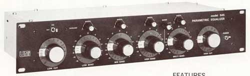
Before my previously posted gyrator EQ projekt I designed UREI clone projekt. I would like equalizer like the best VST software effects like URS EQ bundle:

The most of VST equalizers are parametric, have low noise, high dynamics, very good quality. Maybe with real analog circuits cannot get same result, but we have to build and try. This is my second EQ project of three, the previous one is with gyrators, the last one will permanent Q RANE copy device.
I choose to reproduction of UREI 545 and 546 analog circuits because the users, primary musicians like it, and I want to use for vocal and guitar amplification. The original construction is very old and vintage circuit, the output of UREI EQ shipped with transformer. I changed this output transformer to jFET buffer, I hope this idea will not getting bad result.
This project have modular system like my previous and future projects. The smaller curcuits have to be builded to the large "mainboard" like the cards in the PC computers.
Gallery about the modular design (schematic, PCB):
In this UREI clone project I did not made circuit what is useful alone like the 5 band EQ on gyrator project. This URE EQ is too difficult to make all at one PCB. This is the reason why only modules designed.
The equalizer module:

This is the EQ, must be fit and solder to the one of the mainboards. For the UREI 545 clone I have 4 band mainboard, but for 546 I made 4 and 6 band mainboards. For completion, power filer and power supply required, and I have two PCB for adjustable potentiometers. One of them contains three potentiometers for frequency, Q, and cut/boost adjustment. The second contains 1 or 2 potentiometers only for hi-pass or low pass filters and adjust the output gain.
PCB for three adjustable resistors (Q, Fr, Cut/Boost):

PCB for one or two adjustable resistors for output gain and high pass/low pass filters:

Module called "power filter" for less noise:

For this one module I have three PCBs. One is portrait, on is landscape, and the last is wider than portrait and thinner than landscape version. This module not required but suggested, I you decide you don't need, then just wire the pin 12 to pin 7, and pin 8 to pin 11 on the module plug.
the most important part of the project is the "mainboard". Look the first the 4 and 6 band circuits and PCBs for UREI 546 clone:

The modules - EQs, potentiometers, power filers - must be soldered to the plugs of mainboard:

And i have six band mainboard. Here is a link to see the PCB.
The first version of UREI project is 545 clone:

In this schematic need modules, but the most important, the EQ circuits built to this PCB. For this one, only power filter and adjustable resistor modules required.
The PCB:

This mainboard have only 4 band version, but one of them have three selectable frequency. This part called "multiband".
These EQ circuits are all mono, because to adjust some parameters we need stereo potentiometers for one mono channel only. Lot of adjustable resistors needed. All adjustable band need 3 potentiometers, and one-one for the low pass filter, high pass filter, and the output gain. For 4 channel EQ required 15 potentiometers, for 6 channel need 21.
Finally look at the power supply:

Examples for the C(a) C(b) and C(c) condenser values of 4 channel UREI 545 clone:
UREI546 clone:
- Low cut and high cut: 55k stereo (P4)
- Bandwidth (Q): 10k mono (P2)
- Frequency: 55k stereo (P1)
- Boost/Cut: 10k mono (P4)
UREI545 clone:
- Low cut and high cut: 50k stereo (P4)
- Bandwidth (Q): 10k mono (P2)
- Frequency: 10k stereo (P1)
- Boost/Cut: 10k mono (P4)
For both:
Output gain: 5k mono (P4)
Upgrade:
Here is two tables for 6 band and 10 bands parametric EQ design.
Link to help to design custom bands for the parametric EQ:

The most of VST equalizers are parametric, have low noise, high dynamics, very good quality. Maybe with real analog circuits cannot get same result, but we have to build and try. This is my second EQ project of three, the previous one is with gyrators, the last one will permanent Q RANE copy device.
I choose to reproduction of UREI 545 and 546 analog circuits because the users, primary musicians like it, and I want to use for vocal and guitar amplification. The original construction is very old and vintage circuit, the output of UREI EQ shipped with transformer. I changed this output transformer to jFET buffer, I hope this idea will not getting bad result.
This project have modular system like my previous and future projects. The smaller curcuits have to be builded to the large "mainboard" like the cards in the PC computers.
Gallery about the modular design (schematic, PCB):
In this UREI clone project I did not made circuit what is useful alone like the 5 band EQ on gyrator project. This URE EQ is too difficult to make all at one PCB. This is the reason why only modules designed.
The equalizer module:
This is the EQ, must be fit and solder to the one of the mainboards. For the UREI 545 clone I have 4 band mainboard, but for 546 I made 4 and 6 band mainboards. For completion, power filer and power supply required, and I have two PCB for adjustable potentiometers. One of them contains three potentiometers for frequency, Q, and cut/boost adjustment. The second contains 1 or 2 potentiometers only for hi-pass or low pass filters and adjust the output gain.
PCB for three adjustable resistors (Q, Fr, Cut/Boost):
PCB for one or two adjustable resistors for output gain and high pass/low pass filters:
Module called "power filter" for less noise:
For this one module I have three PCBs. One is portrait, on is landscape, and the last is wider than portrait and thinner than landscape version. This module not required but suggested, I you decide you don't need, then just wire the pin 12 to pin 7, and pin 8 to pin 11 on the module plug.
the most important part of the project is the "mainboard". Look the first the 4 and 6 band circuits and PCBs for UREI 546 clone:
The modules - EQs, potentiometers, power filers - must be soldered to the plugs of mainboard:
And i have six band mainboard. Here is a link to see the PCB.
The first version of UREI project is 545 clone:
In this schematic need modules, but the most important, the EQ circuits built to this PCB. For this one, only power filter and adjustable resistor modules required.
The PCB:
This mainboard have only 4 band version, but one of them have three selectable frequency. This part called "multiband".
These EQ circuits are all mono, because to adjust some parameters we need stereo potentiometers for one mono channel only. Lot of adjustable resistors needed. All adjustable band need 3 potentiometers, and one-one for the low pass filter, high pass filter, and the output gain. For 4 channel EQ required 15 potentiometers, for 6 channel need 21.
Finally look at the power supply:
Examples for the C(a) C(b) and C(c) condenser values of 4 channel UREI 545 clone:
- Low band: C(a) and C(b)= 100nF ; C(c) = 1uF - 30Hz-330Hz
- ow-Mid band: C(a) and C(b)= 27nF ; C(c) = 100nF - 110Hz-1.2kHz
- High-Mid band: C(a) and C(b)= 8nF ; C(c) = 100nF - 390Hz-4.2kHz
- High band: C(a) and C(b)= 2.2nF ; C(c) = 100nF - 1.4kHz-15kHz
- Low band: C(a) and C(b)= 100nF ; C(c) = 100nF - 24Hz-310Hz
- Mid band: C(a) and C(b)= 13nF ; C(c) = 100nF - 190Hz-2.24kHz
- High band: C(a) and C(b)= 2.5nF ; C(c) = 100nF - 960Hz-12.5kHz
- Multiband Low: C(a) and C(b)= 160nF ; C(c) = 100nF - 15Hz-200Hz
- Multiband Mid: C(a) and C(b)= 16nF ; C(c) = 100nF - 150Hz-2kHz
- Multiband High: C(a) and C(b)= 1.6nF ; C(c) = 100nF - 1.5kHz-20kHz
UREI546 clone:
- Low cut and high cut: 55k stereo (P4)
- Bandwidth (Q): 10k mono (P2)
- Frequency: 55k stereo (P1)
- Boost/Cut: 10k mono (P4)
UREI545 clone:
- Low cut and high cut: 50k stereo (P4)
- Bandwidth (Q): 10k mono (P2)
- Frequency: 10k stereo (P1)
- Boost/Cut: 10k mono (P4)
For both:
Output gain: 5k mono (P4)
Upgrade:
Here is two tables for 6 band and 10 bands parametric EQ design.
Link to help to design custom bands for the parametric EQ:
- About EQ by RANE
- Expressions for active EQ designs
- About EQ design
- Windows software to count MFB EQ values
- Very good PDF with expressions and examples
- Another very good PDF with expressions
See also:
- Simulation of UREI LP/HP filter module
- Modular, expandable parametric equalizer based on UREI546
- Simulation of 8 band parametric equalizer
- Simulation and software analysis of UREI 546
- UREI546 parametric EQ like URS VST EQ bundle
- 6 and 10 bands for UREI 546 parametric equalizer
- Math expression for UREI546 parametric EQ design
- Modular equalizer with gyrator filter
- PDF manual of modular gyrator EQ
- PDF manual of UREI 545 and 546 EQ clone
| ||||||||||||||||||||||||||||||||||||||||||||||||||||||||||||||||||||||||||||||||||||||||||||||||||||||||||||||||||||||||||||||||||||||||||
Monday, October 24, 2011
Modular equalizer with gyrator filter
Posting again about my modular gyrator-EQ project. This project not tested yet, but I made 5 channel EQ with gyrators and 10 channel active filters EQ formerly. Look at older pictures:
EQ with gyrator filter is noiseless, simple, and cheap. Because the first version made for guitars or instruments, the adjustment was too fine for me, the "Q" of separated bands was not permanent, one of the EQ band adjusted another frequencies too. Therefore this method is better for home stereo hi-fi instead of instrument amplifications.
After my first gyrator EQ project I made 10 band active filter EQ by RANE. This EQ have permanent Q, the result is much better for instrument amplification. But 10 channel was too much for me, very hard to set the best sound, because I got too much possibilities. Otherwise the noise of this method is much higher than simplest EQ with gyrator filter, but for instruments was much better for me.
Now I have new (untested at this time) equalizer-projects, with 3 different versions. The first is the modular EQ with gyrator, maybe just for home hi-fi. The second is an UREI545 clone parametric EQ, the 3rd is the new modular RANE based permanent Q equalizer. Now I posting about the first type of EQ with noiseless gyrator filers. With current version, I have module with adjustable gyrator circuit only. I made two versions of PCB: the first mounted with one stereo adjustable resistor for home stereo systems, the second is mounted with two mono adjustable resistors for instrument amplification systems to separate left and right channels.
Images:
Stereo gyrator module:


Dual mono gyrator module, the channels (Left, Right) can be adjust separately:

One of the upper modules have to be insert to one of the mainboards.
For 10 bands:

For 5 bands:

To the upper mainboards required one of the gyrator module (stereo or double mono), and module called "power filter" for less noise, and certainly power supply. I have three versions of "power filer" PCB, portrait, landscape, and something between fat and thin :). Look at all pictures about modules.
In this project, very important to able to count out the values of capacitors and resistors. Look at examples, links, and expressions:
5 band EQ:

For 10 band EQ:
Here is the online gyrator calculator:
http://awasteofsalt.com/gyrator/
A little math:

Links for several method to get values of parts:
EQ with gyrator filter is noiseless, simple, and cheap. Because the first version made for guitars or instruments, the adjustment was too fine for me, the "Q" of separated bands was not permanent, one of the EQ band adjusted another frequencies too. Therefore this method is better for home stereo hi-fi instead of instrument amplifications.
After my first gyrator EQ project I made 10 band active filter EQ by RANE. This EQ have permanent Q, the result is much better for instrument amplification. But 10 channel was too much for me, very hard to set the best sound, because I got too much possibilities. Otherwise the noise of this method is much higher than simplest EQ with gyrator filter, but for instruments was much better for me.
Now I have new (untested at this time) equalizer-projects, with 3 different versions. The first is the modular EQ with gyrator, maybe just for home hi-fi. The second is an UREI545 clone parametric EQ, the 3rd is the new modular RANE based permanent Q equalizer. Now I posting about the first type of EQ with noiseless gyrator filers. With current version, I have module with adjustable gyrator circuit only. I made two versions of PCB: the first mounted with one stereo adjustable resistor for home stereo systems, the second is mounted with two mono adjustable resistors for instrument amplification systems to separate left and right channels.
Images:
Stereo gyrator module:

Dual mono gyrator module, the channels (Left, Right) can be adjust separately:
One of the upper modules have to be insert to one of the mainboards.
For 10 bands:
For 5 bands:
To the upper mainboards required one of the gyrator module (stereo or double mono), and module called "power filter" for less noise, and certainly power supply. I have three versions of "power filer" PCB, portrait, landscape, and something between fat and thin :). Look at all pictures about modules.
In this project, very important to able to count out the values of capacitors and resistors. Look at examples, links, and expressions:
5 band EQ:
- 100Hz - 330nF
- 300Hz - 100nF
- 1kHz - 33nF
- 3kHz - 10nF
- 10kHz - 3.3nF
For 10 band EQ:
- All of the 50k adjustable resistors must be changed to 25k.
- For capacitors and resistors look at the table below:
| Hz | C3 and C1 | C4 and C2 | R3 and R1 | R4 and R2 |
| 31 | 6.8 uF | 100 nF | 470 Ohm | 100 kOhm |
| 63 | 3.3 uF | 47 nF | 390 Ohm | 100 kOhm |
| 125 | 1.5 uF | 33 nF | 390 Ohm | 100 kOhm |
| 250 | 680 nF | 22 nF | 330 Ohm | 82 kOhm |
| 500 | 330 nF | 10 nF | 330 Ohm | 100 kOhm |
| 1k | 150 nF | 4.7 nF | 330 Ohm | 100 kOhm |
| 2k | 100 nF | 2.2 nF | 330 Ohm | 82 kOhm |
| 4k | 56 nF | 1 nF | 390 Ohm | 82 kOhm |
| 8k | 22 nF | 470 pF | 390 Ohm | 82 kOhm |
| 16k | 10 nF | 220 pF | 390 Ohm | 100 kOhm |
Here is the online gyrator calculator:
http://awasteofsalt.com/gyrator/
A little math:

Links for several method to get values of parts:
- About EQ by RANE
- Expressions for active EQ designs
- About EQ design
- Windows software to count MFB EQ values
- Very good PDF with expressions and examples
- Another very good PDF with expressions
See also:
- Simulation of UREI LP/HP filter module
- Modular, expandable parametric equalizer based on UREI546
- Simulation of 8 band parametric equalizer
- Simulation and software analysis of UREI 546
- UREI546 parametric EQ like URS VST EQ bundle
- 6 and 10 bands for UREI 546 parametric equalizer
- Math expression for UREI546 parametric EQ design
- Parametric EQ Project - Modular UREI545 and 546
- PDF manual of modular gyrator EQ
- PDF manual of UREI 545 and 546 EQ clone
| ||||||||||||||||||||||||||||||||||||||||||||||||||||||||||||||||||||||||||||||||||||||||||||||||||||||||||||||||||||||||||||||||||||||||||||||||||||||
Saturday, October 22, 2011
Using autorouter for homemade PCB
I made a movie about the autorouter of my favorite electronic CAD software:
When I finished the schematic, I switching to PCB creation and using autorouter. Most of Altium users don't like autorouter, but I think after correct configuration will be really useful for large boards. The most important is the correct strategy and rule settings. Because I made PCB by myself, I need wider lines and high clearance which is the distance between lines on PCB. Finaly I made very high quality photo film of PCB image, and finalized the job with photo resist method.
Here is the movie how to finalize the PCB creation, and a picture gallery about the very good printed circuit board:
My previous movie about the PCB creation :)
The image gallery of the result:
When I finished the schematic, I switching to PCB creation and using autorouter. Most of Altium users don't like autorouter, but I think after correct configuration will be really useful for large boards. The most important is the correct strategy and rule settings. Because I made PCB by myself, I need wider lines and high clearance which is the distance between lines on PCB. Finaly I made very high quality photo film of PCB image, and finalized the job with photo resist method.
Here is the movie how to finalize the PCB creation, and a picture gallery about the very good printed circuit board:
My previous movie about the PCB creation :)
The image gallery of the result:
Subscribe to:
Posts (Atom)


 Posts
Posts


