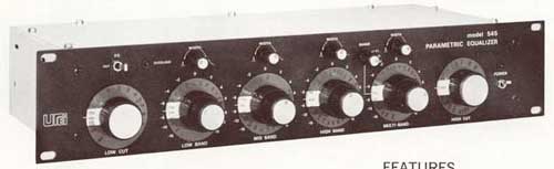
The current project based on the UREI546, but modified. The new design is an expandable parametric equalizer with modular system for smaller PCBs with no limitations. The maximum number of bands are not limited, but the current project made for 4 to 8 band equalizer, with optional input and output gain modules, optional HP/LP filter module, and optional clipping LED module. The design is similar as my previous modular expandable audio mixer or modular amplifier. The current project started with software simulation of filter circuit, and continued to get capacitor values for 8 band EQ by simulation. This is the post where I publish the schematic and PCB design of expandable modular parametric equalizer.
For the expandable feature, 2 mainboards required for this project. The first is for 4 modules, contains connectors for inputs (Conn2), outputs (Conn3), and +/-15V power supply (Conn1). This mainboard designed for 4 band EQ only, without additional modules:

Because between EQ modules and other modules requires serial connection, (not parallel like in the modular audio mixer), the last module on the whole system must be connected to the output bus. This is the reason why W1 and W2 jumpers are required. With these jumpers, the last module must be wired to the system output, without jumpers, the output of module connecting to the input of next module. The jumper must be used only on the last EQ or Output Gain module of the whole system. The connector P2 is 10 pin female connector, the next mainboard must be connected here if required. Conn4....Conn7 is 2x6 L headers for the EQ or Gain modules.
The PCB of first mainboard:

The second mainboard is more simple, contains only one 2x6 L header for one module, on the left one 10 pin male connector, on the right one 10 pin female connector:

W1 and W2 jumpers must used if the connected module is the last on the whole system. If last, the current module output connected to the system output bus by W1 and W2. The one and only exception, if the last module is the clipping detector. If more modules required, this mainboard must be connected to the previous one.
The PCB design:

The modules can be soldered to these two mainboards with 2x6 pins L header. The most important module is the parametric filter:

This filter based on UREI546 with some modifications. The Conn2 must be connected to the mainboard, the Conn1 is the connector for "power filter" module for less noise. This is the reason why the filter capacitor missing from the OpAmp. The C3 is coupling capacitor, 10uF or 22uF is better than 100nF in the original design. No need to change on several EQ modules. For EQ bands with different middle frequency, only 2 pieces of Ca capacitors must be changed. This is the reason, why the footprint accept 200 and 300 mil pins. Sw1 is the bypass switch, D2 diode is connected for the clipping detector bus. P1 adjust Q, P2 adjust the middle frequency, P3 adjust cut/boost of the EQ module.
The PCB:

The module cutted on the bottom because this required for mechanical assembly. The bypass switch and the 3 required potentiometers are soldered to the PCB. D1 is the connector for LED displays the bypassed or connected status of the module. The both mainboards made for stereo circuits, but this module (and currently all others) is mono. The reason of this difference, that in the future I would like to design stereo filters for stereo EQ, but I would like to use these mainboards. The lion in the way, that 4 potentiometers required to adjust the frequency if this EQ module going stereo.
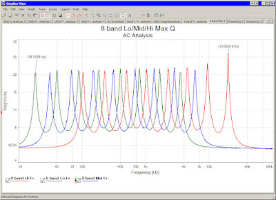
The most important question about this module, the values of Ca (C1 and C2) capacitors. These values depend on the required middle frequency. I have no math expression, but I done software simulation for 8 bands with values.
- Math expression required to get frequency values among the lowest and highest bands. This expression is used for Excel spreadsheet if the first and last frequency, and the number of other bands decided:=IF(C8<$D$5,$D$3*10^((LOG10($D$4)-LOG10($D$3))*(C8-1)/($D$5-1)), IF(C8=$D$5,$D$4,IF(C8>$D$5," ","?")))
- The next is that we need the Ca capacitor value for the module frequency. This value is linear on the logarithmic scale with the frequency, but the best method is the software simulation. Here is an example for 8 band equalizer:

The input of this spreadsheet is on the green fields on the top, contains the highest frequency of the first and last modules, and the number of all EQ modules. I always working with the highest frequency, the middle and the lowest value getting by the software simulation using modified standard capacitor values. - The real value of the module frequencies depend on the standard values of the capacitors. The best result is the software simulation again to getting the lowest and highest values of filters:
- The number of possible requirements are very high. Not only the number of EQ bands, the lowest and highest frequency of the bands can be different. This is the reason, why I can publish and simulated 8 band EQ only. If you like another versions, for example less or more bands, or higher frequency of the lower band, software simulation required to get the capacitor values and the resistor values to setting Q.


With this design the bypass switch with LED, and the header for power filter are available too. The output connected to the clipping detector via D2, like all other filter modules. The C1 capacitor changed to 47pF to get better Q for higher frequency of LP filter. The potentiometers changed from 55kOhm to 22kOhm for smaller adjustment range. High adjustment range is not too important, because numerous adjustable filters can be connected after this module. The highest value of filter depend on C2 and C3 capacitor, what changed from 6.8nf to 4.7nF, but maybe 5.6 nF is the best because the new endpoint of frequency range is around 40kHz what is too much, but the original is around 15 kHz, what is low.
The capacitors of high pass filer is C4 and C5 changed to 470nF instead of the original 220nF to get lowest frequency. With this new value the filter starts from 15Hz, what is too low. Maybe 330nF would be the best, I will do simulation for several values soon.
The result of current AC analysis (470nF and 4.7nF):

The PCB of LP/HP filter module:

The next is a very simple and noiseless preamplifier module with jFET. I really like the sound of this circuit for guitar. This module can be used as first module (for input gain) and (or only) at the end of device as output gain:

This circuit can be bypassed by the switch, and can be ignored if not required.
The PCB:

The last module is the clipping detector what monitor all outputs of applied modules by the pin2 of 2x6 L header:

Clipping detector PCB:

The power filter, required for all modules for less noise except clipping detector:

I have 8 versions of power filter PCB where the difference is only the size of board. This is the version 6 with SMD resistors and transistors:

The required power supply and the PCB:


By these boards can be built like this (for example):
- 4 bands mainboard, 4 pieces of EQ filters with the oroginal values of UREI546 can be the clone of original device but without preamplifier module, LP/HP filter, and clipping detector.
- Start the whole device with 4 band mainboard, use the jFET gain module first, the second is the LP/HP filter module, and continue with 2 parametric EQ module. Connect mainboard 2 to mainboard 1, and use parametric EQ modules. When the maximum number of EQ modules connected, use one more jFET gain module for output gain (with W1 and W2 jumpers) and the last possible module is the clipping detector.
By software simulation the result of these circuits can be changed. The schematic samples on this post maybe set to wide values, but all modules adjustable, so I think this is not a big problem.
On the EQ modules and LP/HP filter modules maybe very important the logarithmic potentiometers. The resistor and capacitor values are linear, but with logarithmic scale of graph. On the simulation and on the schematic I used TL071...TL074, but for the best quality I offer using LT or NE series instead, what is much better for filter designs. For example for single OpAmp use LT1028/LT1128/LT1115, for quad or dual OpAmps can be changed to LT1124/LT1125.
See also:
- Simulation of UREI LP/HP filter module
- Simulation of 8 band parametric equalizer
- Simulation and software analysis of UREI 546
- UREI546 parametric EQ like URS VST EQ bundle
- 6 and 10 bands for UREI 546 parametric equalizer
- Math expression for UREI546 parametric EQ design
- Parametric EQ Project - Modular UREI545 and 546
- Modular equalizer with gyrator filter
- PDF manual of modular gyrator EQ
- PDF manual of UREI 545 and 546 EQ clone
| ||||||||||||||||||||||||||||||||||||||||||||||||||||||||||||||||||||||||||||||||||||||||||||||||||||||||||||||||||||||||||||||||||||||||||




 Posts
Posts


