Showing posts with label eq. Show all posts

Friday, January 6, 2012

Simulation and software analysis of UREI 546

This is my first post about simulation. The reason why I simulated UREI EQ filter, that I cannot found math expression to get parts for more than 4 bands parametric EQ, and I cannot modify the center frequency of original bands.

Finally I did software simulation, what is succeed. The simulation of analog circuits are very fast and exact, very easy to measure and analyze any parameters depending on the parts, easy to get result of parts modifications by graph or by simulated measuring devices. The best is, lot of AC sources and measuring instruments are available, like function generators and oscilloscopes. I used Multisim, because the simulation of Altium is more harder, and I cannot found good examples on the net how to use Altium for simulation. But as I see, the Multisim is very popular (because easy to use, I think):


This is the schematic of one filter from the UREI 546 parametric EQ. Function generator, one channel (yelow) of oscilloscope, and U3 AC voltmeter connected to the input. Second channel of oscilloscope (blue) and U2 AC voltmeter connected to the output. The power supply is the simulation of 2x18V DC power source. On/off switch, and bypass switch included. With simulation, all switches and potentiometers are working well and real time. To see the simulation result, the circuit is very exact, same as like datasheet of original UREI device, with really small differences. The bypass switch or the Cut/Boost potentiometer on center make the output voltage to same with input. I made a movie about simulation:


I wonder, the simulation result is same as the original datasheet, or have some differences. If the result is closed to the original datasheet, I don't need expression for the modifications.

I made new schematic with simple AC voltage source instead of function generator, and I deleted the scope from the output. I used AC analysis on the output point instead of scope. The result is more useful on the graph:


Here is the frequency response of the filter. All modifications can be analyzed and displayed with graph, for example new middle frequency, Q, and Cut/Boost function of EQ between 20 Hz and 20 kHz. Later I analyzed the circuit up to 100 kHz.

With these simulations, I can't compare the results with the original datasheet. Therefore I made 4 bands with exactly same values with the original schematic. I made AC analysis with min, max, and middle frequencies of 4 bands, and compared the maximum and minimum points to the official datasheet:


The red line is the lowest frequency on all 4 bands, the blue is the another side of potentiometer, the possible highest frequency. This is the comparison with the original EQ, where is the upper frequencies are really same, the lower shows small differences. Now I think, because the simulation result and the datasheet are same with small differences, the simulation of this schematic is good idea to modify the original EQ (instead of math expressions).

This is the 5 steps of Q by the original schematic, what is same as than the graph in the datasheet:


The method of software simulation is really big help if I have to modify something. For example, this is the modified possible min and max Q with new values of parts, because for more bands I need better Q:

2 resistors are changed to make new Q values.

Here is the result of the first and last filter, from the lowest to highest possible frequencies of bands:

To make the lowest and highest frequencies of the band closer, the potentiometers changed from original 55 kOhm to new 4.7 kOhm. The lowest band on the graph have 680 nF on the integrators, the highest have 2.2 nF.

With this result, I analyzed the highest band with lower (80%) Q and compared to the result with maximum Q:


The max point of the highest band are much higher than the lowest band, I changed the possible maximum Q to lower, I modified the 80 Ohm resistor to 120 Ohm. To found the ideal resistor value for the maximum Q, I made analysis with several resistor values from 80 Ohm to original 390 Ohm:

This is the first step to design 8 bands parametric equalizer with new values.

See also:

Saturday, October 29, 2011

UREI546 parametric EQ like URS VST EQ bundle plugin

See again the project of parametric UREI EQ project. I posted I really like URS VST audio plugins. I wanted UREI cloned circuit, to make EQ like URS VST. Unfortunately this is impossible, because the required values of parts not available, but I think the differences are not too important because the parameters are adjustable, and maybe with some tricks (parallel connections for example) possible to create something like this. Therefore I choose two parametric EQ plugin from URS bundle, and trying to simulate the values with UREI EQ circuits. I think logarithmic potentiometers required for this simulation.

Look at my new values for 4 bands equalizer:
Lower values in URS VST plugin: 30 Hz, 75 Hz, 800 Hz, 2,5 kHz


Upper values on VST plugin: 400 Hz, 1 kHz, 12,5 kHz, 20 kHz:


The another VST plugin have 5 bands. I have only 4 and 6 bands of EQ PCB, but within 6 bands UREI have to be insert 5 EQ modules only. With this example, from the 5 bands 3 bands are similar. These 3 bands can be adjusted to different settings. Logarithmic potentiometers required again. No standard values of potentiometers like in the tables, but something with similar values will be useful.

Low values: 31 Hz, 75 Hz 3x, 2 kHz.


Upper values: 400 Hz, 12,5 kHz 3x, 20 kHz.


The table with capacitors and adjustable resistors:


I hope it's useful tip.

See also:

Thursday, October 27, 2011

6 and 10 bands for UREI 546 parametric equalizer

It is true, I cannot found really correct math expression to modify the band-frequency of UREI 546 EQ circuit, but I think I have a very useful Excel sheet. I think the not 100% exact expression is not a big problem, because the frequency parameter is adjustable. I have a plan UREI 546 with 6 bands, but I counted out values of potentiometers and capacitors for 10 bands. For 10 bands EQ I will design mainboard later.

The first table for original 4 bands, 6 bands, and 10 bands:


The result is the value of P1 stereo potentiometers for frequency adjustment, and the capacitor of filter C(a) = C(b). If somebody have better expression please send me a message.

Another table just for variations:


See also:


PCB sales of this project
Module name Size
(mm)
Area
(cm2)
PDF SCH PCB image Tested Price (US$)
Des./3D Sim.1 Full2 Sim.1 Full2 Man3
Parametric EQ module
56x61
34
Yes
Yes
Yes
-
-
-
7 14 Yes
2 Potmeter module
31x62
19 Yes
Yes
Yes -
- -
5 12 Yes
3 Potmeter module 41x83 34 Yes Yes Yes - -
-
6 14 Yes
Power filter module V:1
51x22
11
Yes Yes
Yes
- -
-
3 11 Yes
UREI545 clone mainboard V:2
217x143 310
Yes Yes
Yes
- -
-
43 53 Yes
UREI545 clone mainboard V:1 217x198 430
Yes
Yes Yes
-
-
-
59 70 Yes
6 band UREI546 mainboard 173x143
247
Yes Yes Yes -
- - 35 44 Yes
Power supply
121x57
69 Yes Yes
Yes -
- -
11 20 Yes
How to order? Please read the rules carefully!

Wednesday, October 26, 2011

Math expression for UREI546 parametric EQ design

While I found math expression easy for gyrator EQ project, I cannot found mathematical help to customize UREI 545 and 546 EQ circuits. For the EQ module I found nothing, the biggest problem that all parameters can be adjusted by resistors. Therefore I made expression with excel, to count out frequencies to make more than 4 band parametric EQ. The expression is not the best, but working well with several C(a) and C(b) values where C(a) = C(b). If somebody design more than 4 channel UREI 546 EQ, the potentiometes of Q adjustment must be changed too. For example, if the Q adjustment is 10kOhm for 4 bands, for 8 bands must be half (5 or 4,7 kOhm). I hope it's enough and useful for customized parametric EQ design.

Look at the expressions for UREI 546 band-frequencies:

C(a) = C(b), the adjustable resistors for frequency 55kOhm stereo, the permanent resistors are 4,7 kOhm like in the schematic. You have to change the value of C(a) and C(b) capacitors. In the last expression you can get the fpot, which is the frequency depend on the value of potentiometer. The variable Rpot can be set between 0 and 55000 like in the "real life". The result getting in Hz.

The module contains EQ circuit, most be placed to the mainboard PCB:


See also:

Tuesday, October 25, 2011

Parametric EQ Project - Modular UREI545 and 546

Before my previously posted gyrator EQ projekt I designed UREI clone projekt. I would like equalizer like the best VST software effects like URS EQ bundle:

The most of VST equalizers are parametric, have low noise, high dynamics, very good quality. Maybe with real analog circuits cannot get same result, but we have to build and try. This is my second EQ project of three, the previous one is with gyrators, the last one will permanent Q RANE copy device.

I choose to reproduction of UREI 545 and 546 analog circuits because the users, primary musicians like it, and I want to use for vocal and guitar amplification. The original construction is very old and vintage circuit, the output of UREI EQ shipped with transformer. I changed this output transformer to jFET buffer, I hope this idea will not getting bad result.

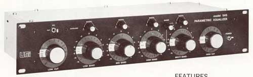
The original UREI 545 EQ:

...and the schematic...

This project have modular system like my previous and future projects. The smaller curcuits have to be builded to the large "mainboard" like the cards in the PC computers.

Gallery about the modular design (schematic, PCB):


In this UREI clone project I did not made circuit what is useful alone like the 5 band EQ on gyrator project. This URE EQ is too difficult to make all at one PCB. This is the reason why only modules designed.

The equalizer module:

This is the EQ, must be fit and solder to the one of the mainboards. For the UREI 545 clone I have 4 band mainboard, but for 546 I made 4 and 6 band mainboards. For completion, power filer and power supply required, and I have two PCB for adjustable potentiometers. One of them contains three potentiometers for frequency, Q, and cut/boost adjustment. The second contains 1 or 2 potentiometers only for hi-pass or low pass filters and adjust the output gain.

PCB for three adjustable resistors (Q, Fr, Cut/Boost):


PCB for one or two adjustable resistors for output gain and high pass/low pass filters:


Module called "power filter" for less noise:

For this one module I have three PCBs. One is portrait, on is landscape, and the last is wider than portrait and thinner than landscape version. This module not required but suggested, I you decide you don't need, then just wire the pin 12 to pin 7, and pin 8 to pin 11 on the module plug.

the most important part of the project is the "mainboard". Look the first the 4 and 6 band circuits and PCBs for UREI 546 clone:


The modules - EQs, potentiometers, power filers - must be soldered to the plugs of mainboard:


And i have six band mainboard. Here is a link to see the PCB.

The first version of UREI project is 545 clone:

In this schematic need modules, but the most important, the EQ circuits built to this PCB. For this one, only power filter and adjustable resistor modules required.

The PCB:

This mainboard have only 4 band version, but one of them have three selectable frequency. This part called "multiband".

These EQ circuits are all mono, because to adjust some parameters we need stereo potentiometers for one mono channel only. Lot of adjustable resistors needed. All adjustable band need 3 potentiometers, and one-one for the low pass filter, high pass filter, and the output gain. For 4 channel EQ required 15 potentiometers, for 6 channel need 21.

Finally look at the power supply:


Examples for the C(a) C(b) and C(c) condenser values of 4 channel UREI 545 clone:

  • Low band: C(a) and C(b)= 100nF ; C(c) = 1uF - 30Hz-330Hz
  • ow-Mid band: C(a) and C(b)= 27nF ; C(c) = 100nF - 110Hz-1.2kHz
  • High-Mid band: C(a) and C(b)= 8nF ; C(c) = 100nF - 390Hz-4.2kHz
  • High band: C(a) and C(b)= 2.2nF ; C(c) = 100nF - 1.4kHz-15kHz
The 3 band section of UREI 545:
  • Low band: C(a) and C(b)= 100nF ; C(c) = 100nF - 24Hz-310Hz
  • Mid band: C(a) and C(b)= 13nF ; C(c) = 100nF - 190Hz-2.24kHz
  • High band: C(a) and C(b)= 2.5nF ; C(c) = 100nF - 960Hz-12.5kHz
The 4th band of 545 is the multiband section of EQ:
  • Multiband Low: C(a) and C(b)= 160nF ; C(c) = 100nF - 15Hz-200Hz
  • Multiband Mid: C(a) and C(b)= 16nF ; C(c) = 100nF - 150Hz-2kHz
  • Multiband High: C(a) and C(b)= 1.6nF ; C(c) = 100nF - 1.5kHz-20kHz
The values of required potentiometer modules:

UREI546 clone:
- Low cut and high cut: 55k stereo (P4)
- Bandwidth (Q): 10k mono (P2)
- Frequency: 55k stereo (P1)
- Boost/Cut: 10k mono (P4)

UREI545 clone:
- Low cut and high cut: 50k stereo (P4)
- Bandwidth (Q): 10k mono (P2)
- Frequency: 10k stereo (P1)
- Boost/Cut: 10k mono (P4)

For both:
Output gain: 5k mono (P4)

Upgrade:
Here is two tables for 6 band and 10 bands parametric EQ design.

Link to help to design custom bands for the parametric EQ:
I think its enough if you want simple but very good quality gyrator EQ circuits.

See also:

PCB sales of this project
Module name Size
(mm)
Area
(cm2)
PDF SCH PCB image Tested Price (US$)
Des./3D Sim.1 Full2 Sim.1 Full2 Man3
Parametric EQ module
56x61
34
Yes
Yes
Yes
-
-
-
7 14 Yes
2 Potmeter module
31x62
19 Yes
Yes
Yes -
- -
5 12 Yes
3 Potmeter module 41x83 34 Yes Yes Yes - -
-
6 14 Yes
Power filter module V:1
51x22
11
Yes Yes
Yes
- -
-
3 11 Yes
UREI545 clone mainboard V:2
217x143 310
Yes Yes
Yes
- -
-
43 53 Yes
UREI545 clone mainboard V:1 217x198 430
Yes
Yes Yes
-
-
-
59 70 Yes
6 band UREI546 mainboard 173x143
247
Yes Yes Yes -
- - 35 44 Yes
Power supply
121x57
69 Yes Yes
Yes -
- -
11 20 Yes
How to order? Please read the rules carefully!

Monday, October 24, 2011

Modular equalizer with gyrator filter

Posting again about my modular gyrator-EQ project. This project not tested yet, but I made 5 channel EQ with gyrators and 10 channel active filters EQ formerly. Look at older pictures:


EQ with gyrator filter is noiseless, simple, and cheap. Because the first version made for guitars or instruments, the adjustment was too fine for me, the "Q" of separated bands was not permanent, one of the EQ band adjusted another frequencies too. Therefore this method is better for home stereo hi-fi instead of instrument amplifications.

After my first gyrator EQ project I made 10 band active filter EQ by RANE. This EQ have permanent Q, the result is much better for instrument amplification. But 10 channel was too much for me, very hard to set the best sound, because I got too much possibilities. Otherwise the noise of this method is much higher than simplest EQ with gyrator filter, but for instruments was much better for me.

Now I have new (untested at this time) equalizer-projects, with 3 different versions. The first is the modular EQ with gyrator, maybe just for home hi-fi. The second is an UREI545 clone parametric EQ, the 3rd is the new modular RANE based permanent Q equalizer. Now I posting about the first type of EQ with noiseless gyrator filers. With current version, I have module with adjustable gyrator circuit only. I made two versions of PCB: the first mounted with one stereo adjustable resistor for home stereo systems, the second is mounted with two mono adjustable resistors for instrument amplification systems to separate left and right channels.

Images:
Stereo gyrator module:
Link

Dual mono gyrator module, the channels (Left, Right) can be adjust separately:


One of the upper modules have to be insert to one of the mainboards.
For 10 bands:


For 5 bands:


To the upper mainboards required one of the gyrator module (stereo or double mono), and module called "power filter" for less noise, and certainly power supply. I have three versions of "power filer" PCB, portrait, landscape, and something between fat and thin :). Look at all pictures about modules.

In this project, very important to able to count out the values of capacitors and resistors. Look at examples, links, and expressions:

5 band EQ:
  • 100Hz - 330nF
  • 300Hz - 100nF
  • 1kHz - 33nF
  • 3kHz - 10nF
  • 10kHz - 3.3nF
The upper values are valid for all of the C(a) capacitors in this schematic:


For 10 band EQ:
  • All of the 50k adjustable resistors must be changed to 25k.
  • For capacitors and resistors look at the table below:
HzC3 and C1C4 and C2R3 and R1R4 and R2
316.8 uF100 nF470 Ohm100 kOhm
633.3 uF47 nF390 Ohm100 kOhm
1251.5 uF33 nF390 Ohm100 kOhm
250680 nF22 nF330 Ohm82 kOhm
500330 nF10 nF330 Ohm100 kOhm
1k150 nF4.7 nF330 Ohm100 kOhm
2k100 nF2.2 nF330 Ohm82 kOhm
4k56 nF1 nF390 Ohm82 kOhm
8k22 nF470 pF390 Ohm82 kOhm
16k10 nF220 pF390 Ohm100 kOhm

Here is the online gyrator calculator:
http://awasteofsalt.com/gyrator/

A little math:


Links for several method to get values of parts:
I think its enough if you want simple but very good quality gyrator EQ circuits.

See also:

PCB sales of this project
Module name Size
(mm)
Area
(cm2)
PDF SCH PCB image Tested Price (US$)
Des./3D Sim.1 Full2 Sim.1 Full2 Man3
Power filter V:1
51x22 11 Yes
Yes
Yes - - - 3 11 Yes
Power filter V:2 27x41 11 Yes Yes Yes
-
-
- 3 11 Yes
Power filter V:3 21x45
9 Yes Yes
Yes - - - 3 11 Yes
Power supply
212x57 69 Yes
Yes
Yes Yes - - 11 20 Yes
5 band gyrator EQ
132x122
161 Yes Yes Yes -
- - 23 33 Yes
Stereo gyrator EQ module
30x61 18 Yes
Yes Yes
- - - 4 12 Yes
Double mono gyrator EQ module
30x65
20
Yes Yes Yes - - - 5 12 Yes
5 band EQ mainboard
75x95 71
Yes
Yes Yes - - -
11 20 Yes
10 band EQ mainboard
152x63
96
Yes
Yes Yes - - - 15 24 Yes
How to order? Please read the rules carefully!