
The most of VST equalizers are parametric, have low noise, high dynamics, very good quality. Maybe with real analog circuits cannot get same result, but we have to build and try. This is my second EQ project of three, the previous one is with gyrators, the last one will permanent Q RANE copy device.
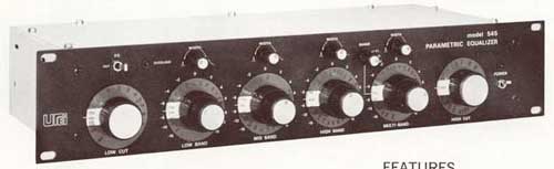
I choose to reproduction of UREI 545 and 546 analog circuits because the users, primary musicians like it, and I want to use for vocal and guitar amplification. The original construction is very old and vintage circuit, the output of UREI EQ shipped with transformer. I changed this output transformer to jFET buffer, I hope this idea will not getting bad result.
This project have modular system like my previous and future projects. The smaller curcuits have to be builded to the large "mainboard" like the cards in the PC computers.
Gallery about the modular design (schematic, PCB):
In this UREI clone project I did not made circuit what is useful alone like the 5 band EQ on gyrator project. This URE EQ is too difficult to make all at one PCB. This is the reason why only modules designed.
The equalizer module:

This is the EQ, must be fit and solder to the one of the mainboards. For the UREI 545 clone I have 4 band mainboard, but for 546 I made 4 and 6 band mainboards. For completion, power filer and power supply required, and I have two PCB for adjustable potentiometers. One of them contains three potentiometers for frequency, Q, and cut/boost adjustment. The second contains 1 or 2 potentiometers only for hi-pass or low pass filters and adjust the output gain.
PCB for three adjustable resistors (Q, Fr, Cut/Boost):

PCB for one or two adjustable resistors for output gain and high pass/low pass filters:

Module called "power filter" for less noise:

For this one module I have three PCBs. One is portrait, on is landscape, and the last is wider than portrait and thinner than landscape version. This module not required but suggested, I you decide you don't need, then just wire the pin 12 to pin 7, and pin 8 to pin 11 on the module plug.
the most important part of the project is the "mainboard". Look the first the 4 and 6 band circuits and PCBs for UREI 546 clone:

The modules - EQs, potentiometers, power filers - must be soldered to the plugs of mainboard:

And i have six band mainboard. Here is a link to see the PCB.
The first version of UREI project is 545 clone:

In this schematic need modules, but the most important, the EQ circuits built to this PCB. For this one, only power filter and adjustable resistor modules required.
The PCB:

This mainboard have only 4 band version, but one of them have three selectable frequency. This part called "multiband".
These EQ circuits are all mono, because to adjust some parameters we need stereo potentiometers for one mono channel only. Lot of adjustable resistors needed. All adjustable band need 3 potentiometers, and one-one for the low pass filter, high pass filter, and the output gain. For 4 channel EQ required 15 potentiometers, for 6 channel need 21.
Finally look at the power supply:

Examples for the C(a) C(b) and C(c) condenser values of 4 channel UREI 545 clone:
- Low band: C(a) and C(b)= 100nF ; C(c) = 1uF - 30Hz-330Hz
- ow-Mid band: C(a) and C(b)= 27nF ; C(c) = 100nF - 110Hz-1.2kHz
- High-Mid band: C(a) and C(b)= 8nF ; C(c) = 100nF - 390Hz-4.2kHz
- High band: C(a) and C(b)= 2.2nF ; C(c) = 100nF - 1.4kHz-15kHz
- Low band: C(a) and C(b)= 100nF ; C(c) = 100nF - 24Hz-310Hz
- Mid band: C(a) and C(b)= 13nF ; C(c) = 100nF - 190Hz-2.24kHz
- High band: C(a) and C(b)= 2.5nF ; C(c) = 100nF - 960Hz-12.5kHz
- Multiband Low: C(a) and C(b)= 160nF ; C(c) = 100nF - 15Hz-200Hz
- Multiband Mid: C(a) and C(b)= 16nF ; C(c) = 100nF - 150Hz-2kHz
- Multiband High: C(a) and C(b)= 1.6nF ; C(c) = 100nF - 1.5kHz-20kHz
UREI546 clone:
- Low cut and high cut: 55k stereo (P4)
- Bandwidth (Q): 10k mono (P2)
- Frequency: 55k stereo (P1)
- Boost/Cut: 10k mono (P4)
UREI545 clone:
- Low cut and high cut: 50k stereo (P4)
- Bandwidth (Q): 10k mono (P2)
- Frequency: 10k stereo (P1)
- Boost/Cut: 10k mono (P4)
For both:
Output gain: 5k mono (P4)
Upgrade:
Here is two tables for 6 band and 10 bands parametric EQ design.
Link to help to design custom bands for the parametric EQ:
- About EQ by RANE
- Expressions for active EQ designs
- About EQ design
- Windows software to count MFB EQ values
- Very good PDF with expressions and examples
- Another very good PDF with expressions
See also:
- Simulation of UREI LP/HP filter module
- Modular, expandable parametric equalizer based on UREI546
- Simulation of 8 band parametric equalizer
- Simulation and software analysis of UREI 546
- UREI546 parametric EQ like URS VST EQ bundle
- 6 and 10 bands for UREI 546 parametric equalizer
- Math expression for UREI546 parametric EQ design
- Modular equalizer with gyrator filter
- PDF manual of modular gyrator EQ
- PDF manual of UREI 545 and 546 EQ clone
| ||||||||||||||||||||||||||||||||||||||||||||||||||||||||||||||||||||||||||||||||||||||||||||||||||||||||||||||||||||||||||||||||||||||||||


Making PCBs at home, it can save money, but the quality is hard to guranty, and usually there is no solder masker, also looks very rough.
ReplyDeleteHowever, for better efficiency try to buy PCBs from a special PCB fab. Here recommend a very good PCB fab, their site is : www.pcbway.com/e
As one of the most experienced PCB manufacturers in China, we pride ourselves to be your best business partners as well as good friends in the every aspect of your PCB needs.