The simplest preamplifier with very high gain contains only 1 dual opamp. The sound quality depend on the amplifier circuit. Recommended to try the PCB with TL072, NE5532, or LT1124. Maybe the maximum gain will lower with better quality circuits, but the noise and the sound quality will better with NExxxx or LTxxxx dual operational amplifiers. The board of this schematic contains potentiometers for gain and volume adjustment, and 6,3 mm stereo jack input. Stereo circuit, like all others except microphone preamp. The board contains all required potentiometers, jack input, and two switches for stereo/mono and true-bypass. The switches have to be soldered to the small PCB with 12 pins "L" connector. This switch-board have to be connected to the preamplifier's PCB if required, if not, just wire the required pins of the connector on the preamp-board to ignore these switches. This very simple schematic have very big gain, but for microphone is not enough, for guitars too much. The sound of circuit with TL072 dual opamp is good for mixed music, but not for instruments like guitar or guitar effect. This is the reason why I recommended for home music listening. The "P1" connector on board is option for LED output to indicate if something connected to the jack-input.
Schematic:

PCB:

The second version of above schematic with two single operational amplifier instead of one dual:

This PCB is bigger, but very good solution for single operational amplifiers. The ultra low noise single OpAmps are not cheaper, but easier to find than dual. LF356, OPAxxx, LT1028, LT1115 (instead of dual LT1124) are the alternatives for better solutions than the cheapest TL071. The board contains one "power filter" circuit to reduce the noise of power supply.
Finally I have version no.3 for the Opamp solutions. The stereo circuit contains 2 single Opamps instead of one dual like above, but two power filter circuits included, one-one for both operation amplifiers. This solution is better for ultra low noise circuits like LT1028 or LT11115.

The small circuit contains switches:

This circuit contains 3 switches, but SW1 and SW2 are same. Only the place of these parts are different. If required only one switch, use SW3 only.
The PCB of switches:

This really small board required for all preamplifiers, except Dual-jFET preamplifier. If the switches are not required, just wire the correct pins of the P1 connector on the amplifier's board.
The dual-jFET preamplifier.
This is my favorite schematic for guitars or guitar-effects. The circuit contains one dual jFET for stereo input. No noise, good dynamics, warm sound. No symmetrical power required, therefore the power filter is smaller and simpler. The gain and volume potentiometers, and the stereo jack input connected to the PCB. The maximum gain is lower than the Opamp preamplifier's, but enough for guitars, guitar effects, and keyboards, or another instruments, except microphones.
See the schematic:

PCB:

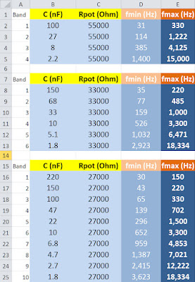
This PCB have no bypass and stereo/mono switches. Maybe later will be included. The originally planned part 2N3958 Dual jFET is not available now, but any low frequency dual N-channel jFET compatible with this solution. Here is the table to find another dual jFET.
The next schematic is a microphone preamplifier with very cheap and good quality operational amplifier INA217. This is the recommended application schematic of this integrated instrument preamplifier. The PCB contains two mono potentiometers for gain and volume, and one 6,3mm jack input for unbalanced inputs like guitars. The switch-module contains only one switch to select between unbalanced/balanced inputs. The unbalanced input is the 6,3 jack, the balanced have 3 pins connector, and external XLR input required. For 48V phantom power required an independent external switch to the case if you want to use condenser microphones.

Very cheap and good quality circuit. No noise, no feedback, very high gain, good dynamics. Compared to cheap Phonix mixer, this circuit was much better with Sennheiser and Behringer dynamic vocal microphones. The 48V input for phantom power included to the PCB but power supply required for this feature. Unbalanced to balanced converter circuit included after jack input to the board. This is cheap and simple converter, but with the recommendation of Jensen. Later will be changed this converter to better one. The PCB contains 3 integrated circuits, but one power filter circuit included.
The PCB:

The PCBs of these preamplifier circuits drilled with same positions on the bottom. With these holes possible to fix to the case of mixer or preamplifiers. Later, all of these preamplifiers modified to module of audio mixer. The inputs, outputs, and powers wired to the pins of connectors.
Finally here is the recommended +-15V power supply:

PCB:

The PDF about preamplifier projects.
As I posted, all preamplifiers converted to module of audio mixer with 12 pins connectors. With these connectors the preaplifiers can be connected to the mainboards of mixer. All of the power filter circuits connected as module to the new PCB of preamp-modules. The mixer-mainboard contains only mixing circuits and 2 stereo line outputs:

Gallery about preamplifiers:
Picasa gallery about modular mixer:
| ||||||||||||||||||||||||||||||||||||||||||||||||||||||||||||||||||||||||||||||||||||||||||||||||||||||||||||||||||||||||||||||||||||||||||


